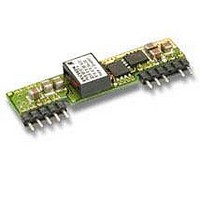
PMB8818TP Ericsson Power Modules, PMB8818TP Datasheet - Page 30

PMB8818TP
Manufacturer Part Number
PMB8818TP
Description
DC/DC Power Supply Single-OUT 0.75V to 5.5V 16A 80W 10-Pin
Manufacturer
Ericsson Power Modules
Type
Step Downr
Series
PMBr
Datasheet
1.PMB8818TP.pdf
(32 pages)
Specifications of PMB8818TP
Output Current
16 A
Output Voltage
0.75 to 5.5 V
Input Voltage
12 V
Number Of Outputs
1
Output Power
80 W
Input Voltage Range
8.3 V to 16 V
Output Voltage (channel 1)
0.75 V to 5.5 V
Output Current (channel 1)
16 A
Package / Case Size
SIP
Output Type
Non-Isolated
Lead Free Status / Rohs Status
Lead free / RoHS Compliant
The PMB 8000 series regulator can accept up to 8mF of
capacitive load on the output at full load. This gives <500
mF/A of I
to consider the selection of output capacitors; the resulting
behavior is a combination of the amount of capacitance and
ESR.
A combination of low ESR and output capacitance
exceeding 8mF for PMB 8818 can cause the regulator into
over current protection mode (hick-up) due to high start up
current. The output filter must therefore be designed without
exceeding the above stated capacitance levels if the ESR is
lower then
30-40 mΩ.
Parallel Operation
The PMB 8000 Series DC/DC regulators can be connected
in parallel with a common input. Paralleling is accomplished
by connecting the output voltage pins directly and using
a load sharing device on the input. Layout considerations
should be made to avoid load imbalance. For more details
on paralleling, please consult your local applications support.
Thermal Considerations
PMB 8818T P Datasheet
General
The PMB 8000 Series DC/DC regulators are designed
to operate in a variety of thermal environments, however
sufficient cooling should be provided to help ensure reliable
operation. Heat is removed by conduction, convection and
radiation to the surrounding environment. Increased airflow
enhances the heat transfer via convection. Proper cooling
can be verified by measuring the temperature
at the reference point (T
The PMB 8000 thermal testing is performed with the
product mounted on an FR4 board 254 �� 254 mm with 8
layers of 35 mm copper. Airflow is perpendicular to the T
side.
O
. When using that large capacitance it is important
1
ref
).
T ref
(max 115 °C)
�� 254 mm with 8
254 mm with 8
ref
0
E.g V output at 1 m/s, full load, 1 V in:
A. (( ) - 1) �� 80 W = 5.11 W
B. 5.11 W �� 7.2 °C/W = 36.8 °C
C. 115 °C - 36.8 °C = max ambient temperature is 78.2 °C
The real temperature will be dependent on several factors,
like PCB size and type, direction of airflow, air turbulence
etc. It is recommended to verify the temperature by testing.
Calculation of ambient temperature
By using the thermal resistance the maximum allowed
ambient temperature can be calculated.
1. T he powerloss is calculated by using the formula
2. F ind the value of the thermal resistance for each product
3. M ax allowed calculated ambient temperature is: Max
( (1/η) - 1) �� output power = power losses.
η = efficiency of converter. E.g 88% = 0.88
in t he diagram by using the airflow speed at the output
section o f the converter. Take the thermal resistance x
powerloss to g et the temperature increase.
T
0.94
ref
airflow
1
of DC/DC regulator – temperature increase.
Thermal resistance vs. airspeed measured at the regulator.
choke
EN/LZT 146 066 R2A © Ericsson Power Modules, April 2007
Test board


