AD1671JP Analog Devices Inc, AD1671JP Datasheet - Page 2
AD1671JP
Manufacturer Part Number
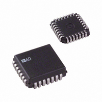
AD1671JP
Description
ADC Single Pipelined 1.25MSPS 12-Bit Parallel 28-Pin PLCC
Manufacturer
Analog Devices Inc
Datasheet
1.AD1671JP.pdf
(16 pages)
Specifications of AD1671JP
Package
28PLCC
Resolution
12 Bit
Sampling Rate
1250 KSPS
Architecture
Pipelined
Number Of Analog Inputs
1
Digital Interface Type
Parallel
Input Type
Voltage
Polarity Of Input Voltage
Unipolar|Bipolar
Rohs Status
RoHS non-compliant
Number Of Bits
12
Sampling Rate (per Second)
1.25M
Data Interface
Parallel
Number Of Converters
2
Power Dissipation (max)
750mW
Voltage Supply Source
Analog and Digital, Dual ±
Operating Temperature
0°C ~ 70°C
Mounting Type
Surface Mount
Package / Case
28-LCC (J-Lead)
Lead Free Status / RoHS Status
Available stocks
Company
Part Number
Manufacturer
Quantity
Price

Part Number:
AD1671JP
Manufacturer:
ADI/亚德诺
Quantity:
20 000
Company:
Part Number:
AD1671JPZ
Manufacturer:
AD
Quantity:
1 000


DC SPECIFICATIONS
Parameter
RESOLUTION
CONVERSION TIME
ACCURACY
TEMPERATURE COEFFICIENTS
POWER SUPPLY REJECTION
ANALOG INPUT
INTERNAL VOLTAGE REFERENCE
LOGIC INPUTS
LOGIC OUTPUTS
POWER SUPPLIES
POWER CONSUMPTION
TEMPERATURE RANGE (SPECIFIED)
NOTES
1
2
3
4
5
6
Specifications subject to change without notice.
AD1671–SPECIFICATIONS
Adjustable to zero with external potentiometers.
Includes internal voltage reference error.
+25 C to T
Excludes internal reference drift.
Change in gain error as a function of the dc supply voltage.
Tested under static conditions. See Figure 15 for typical curve of I
Integral Nonlinearity (INL)
Differential Nonlinearity (DNL)
No Missing Codes
Unipolar Offsets
Bipolar Zero
Gain Error
Unipolar Offset
Bipolar Zero
Gain Error
Gain Error
V
V
V
Input Ranges
Input Resistance
Input Capacitance
Aperture Delay
Aperture Jitter
Output Voltage
Output Current
High Level Input Voltage, V
Low Level Input Voltage, V
High Level Input Current, I
Low Level Input Current, I
Input Capacitance, C
High Level Output Voltage, V
Low Level Output Voltage, V
Operating Voltages
Operating Current
J/K
A
S
CC
LOGIC
EE
V
(S Grade)
(S Grade)
(S Grade)
(S Grade)
(S Grade)
(S Grade)
(S Grade)
Bipolar
Unipolar
(0 V to +2.5 V or 2.5 V Range)
(0 V to +5.0 V or 5 V Range)
Unipolar Mode
Bipolar Mode
V
V
I
I
I
CC
LOGIC
EE
CC
LOGIC
EE
(–5 V
(+5 V
(+5 V
MIN
6
1, 2
3
4
and +25 C to T
1
0.25 V)
0.25 V)
(+25 C)
(+25 C)
0.25 V)
1
(+25 C)
IN
MAX
LL
IL
IH
IH
OL
OH
5
(V
(V
(I
IN
IN
(I
OL
3
OH
= 0 V)
= V
(T
= 1.6 mA)
MIN
= 0.5 mA)
LOGIC
to T
)
MAX
with V
LOGIC
CC
Min
12
11
11 Bits Guaranteed
–2.5
–5.0
0
0
8
2.475
2.0
–10
–10
2.4
+4.75
+4.5
–4.75
0
–40
–55
= +5 V
vs. load capacitance at maximum t
5%, V
AD1671J/A/S
Typ
0.1
10
10
10
15
20
2.5
5
55
3
–55
570
–2–
LOGIC
1.5
= +5 V
C
.
Max
800
0.35
+2.5
+5.0
+2.5
+5.0
12
2.525
+2.5
+1.0
0.8
+10
+10
0.4
+5.25
+5.5
–5.25
68
5
–68
750
+70
+85
+125
2.5
3.0
9
10
25
25
25
30
30
40
20
4
5
4
5
4
5
10%, V
EE
= –5 V
–2.5
0
Min
12
12
12 Bits Guaranteed
–5.0
0
8
2.475
2.0
–10
–10
2.4
+4.75
+4.5
–4.75
0
–40
–55
5%, unless otherwise noted)
AD1671K
Typ
0.1
10
10
10
15
20
2.5
5
55
3
–55
570
0.7
Max
800
0.35
+2.5
+5.0
+2.5
+5.0
12
2.525
+2.5
+1.0
0.8
+10
+10
0.4
+5.25
+5.5
–5.25
68
5
–68
750
+70
+85
+125
2.5
9
10
25
25
30
20
4
4
4
Bits
ns
LSB
Bits
LSB
LSB
% FSR
ppm/ C
ppm/ C
ppm/ C
ppm/ C
LSB
LSB
LSB
Volts
Volts
Volts
Volts
M
k
pF
ns
Volts
mA
mA
Volts
Volts
pF
Volts
Volts
Volts
Volts
mA
mA
mA
mW
Units
ps
Volts
REV. B
C
C
C
A
A
Related parts for AD1671JP
Image
Part Number
Description
Manufacturer
Datasheet
Request
R

Part Number:
Description:
±1.7g Dual-Axis IMEMS Accelerometer Evaluation Board
Manufacturer:
Analog Devices Inc
Datasheet:

Part Number:
Description:
Inertial Sensor Evaluation System
Manufacturer:
Analog Devices Inc
Datasheet:
Part Number:
Description:
Manufacturer:
Analog Devices Inc
Datasheet:
Part Number:
Description:
Manufacturer:
Analog Devices Inc
Datasheet:
Part Number:
Description:
Manufacturer:
Analog Devices Inc
Datasheet:
Part Number:
Description:
Manufacturer:
Analog Devices Inc
Datasheet:
Part Number:
Description:
Manufacturer:
Analog Devices Inc
Datasheet:
Part Number:
Description:
Manufacturer:
Analog Devices Inc
Datasheet:
Part Number:
Description:
Manufacturer:
Analog Devices Inc
Datasheet:
Part Number:
Description:
Manufacturer:
Analog Devices Inc
Datasheet:
Part Number:
Description:
Manufacturer:
Analog Devices Inc
Datasheet:
Part Number:
Description:
Manufacturer:
Analog Devices Inc
Datasheet:
Part Number:
Description:
Manufacturer:
Analog Devices Inc
Datasheet: