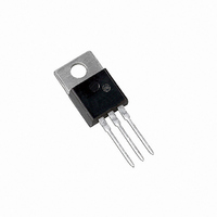
MJE5851G ON Semiconductor, MJE5851G Datasheet - Page 5

MJE5851G
Manufacturer Part Number
MJE5851G
Description
TRANS PWR PNP 8A 350V TO220AB
Manufacturer
ON Semiconductor
Series
SWITCHMODE™r
Datasheet
1.MJE5852G.pdf
(8 pages)
Specifications of MJE5851G
Transistor Type
PNP
Current - Collector (ic) (max)
8A
Voltage - Collector Emitter Breakdown (max)
350V
Vce Saturation (max) @ Ib, Ic
5V @ 3A, 8A
Dc Current Gain (hfe) (min) @ Ic, Vce
5 @ 5A, 5V
Power - Max
80W
Mounting Type
Through Hole
Package / Case
TO-220-3 (Straight Leads)
Transistor Polarity
PNP
Mounting Style
Through Hole
Collector- Emitter Voltage Vceo Max
350 V
Emitter- Base Voltage Vebo
6 V
Maximum Dc Collector Current
8 A
Power Dissipation
80 W
Continuous Collector Current
8 A
Dc Collector/base Gain Hfe Min
15
Lead Free Status / RoHS Status
Lead free / RoHS Compliant
Current - Collector Cutoff (max)
-
Frequency - Transition
-
Lead Free Status / Rohs Status
Lead free / RoHS Compliant
Other names
MJE5851GOS
I
I
V
C
B
Figure 7. Inductive Switching Measurements
CE
SEE ABOVE FOR
DETAILED CONDITIONS
L
R
−10 V
0
coil
coil
PW Varied to Attain
I
C
= 80 mH, V
= 0.7 W
= 100 mA
V
CEO(sus)
20
PUT
IN-
1
90% I
CC
TUT
INDUCTIVE TEST CIRCUIT
= 10 V
B1
t
sr
EQUIVALENT
1
2
V
1N4937
10%
0.1 W
RS =
CEM
OR
V
clamp
TIME
+ V
90%
−V adjusted to obtain desired I
+ V adjusted to obtain desired V
I
CM
0
Table 1. Test Conditions for Dynamic Performance
INPUT
50 W
2 W
I
CM
t
rv
V
R
L
CC
t
coil
coil
c
MJE5850, MJE5851, MJE5852
t
fi
L
R
V
V
coil
CC
coil
RBSOA AND INDUCTIVE SWITCHING
V
CEM
CE
I
C
= 180 mH
= 20 V
= 0.05 W
0.1 mF
0.2 mF
0.2 mF
10%
I
500 W
CM
1/2 W
t
V
ti
I
clamp
CM
http://onsemi.com
TIM
2%
I
CM
E
OUTPUT WAVEFORMS
V
CEM
500 W
1/2 W
t
1
B1
BE(off)
1.0
0.8
0.6
0.4
0.2
5
0.0033 mF
0.0025 mF
0
500 W
1/2 W
1/2 W
t
500 W
f
0
t
2
V
R
clamp
B
t
c
adjusted to attain desired I
25°C
t
Clamped
f
t
sv
1
t
= 250 V
Figure 8. Inductive Switching Times
V
100°C
clamp
t
c
MJE15028
V
+ V
MJE15029
− V
100°C
BE
2
t
, BASE−EMITTER VOLTAGE (VOLTS)
+
−
50 mF
50 mF
0.1 mF
0.1 mF
1N4934
1 W 2
Scope — Tektronix
475 or Equivalent
t
Obtain I
W
−
+
1
Test Equipment
t
t
1
2
Adjusted to
3
≈
≈
L
L
B1
coil
coil
V
C
V
Clamp
CC
(I
(I
4
CM
CM
1
2
)
)
t
sv
25°C
5
1
2
RESISTIVE SWITCHING
RESISTIVE TEST CIRCUIT
I
the resistive test circuit.
Use inductive switching
B1
driver as the input to
I
I
T
6
C
C
TURN−OFF TIME
V
R
Pulse Width = 10
ms
J
TURN−ON TIME
obtain the forced
/I
I
= 4 A
CC
L
= 25°C
B1
B
h
= 62 W
FE
= 4
adjusted to
= 250 V
TUT
desired
7
1
2
8
3.0
2.7
2.4
2.1
1.8
1.5
1.2
0.9
0.6
0.3
0
R
V
L
CC


