DTA114GKAT146 Rohm Semiconductor, DTA114GKAT146 Datasheet - Page 2
DTA114GKAT146
Manufacturer Part Number
DTA114GKAT146
Description
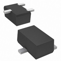
TRANS PNP 50V 100MA SOT-346
Manufacturer
Rohm Semiconductor
Datasheet
1.DTA114GUAT106.pdf
(3 pages)
Specifications of DTA114GKAT146
Transistor Type
PNP - Pre-Biased
Current - Collector (ic) (max)
100mA
Voltage - Collector Emitter Breakdown (max)
50V
Resistor - Base (r1) (ohms)
10K
Dc Current Gain (hfe) (min) @ Ic, Vce
30 @ 5mA, 5V
Vce Saturation (max) @ Ib, Ic
300mV @ 500µA, 10mA
Frequency - Transition
250MHz
Power - Max
200mW
Mounting Type
Surface Mount
Package / Case
SC-59-3, SMT3, SOT-346, TO-236
Digital
PNP SC-59
Collector Emitter Voltage V(br)ceo
50V
Power Dissipation Pd
200mW
Dc Collector Current
10mA
Operating Temperature Range
-55°C To +150°C
Transistor Case Style
SOT-346
No.
RoHS Compliant
Transistor Polarity
PNP
Dc Current Gain Hfe
30
Rohs Compliant
Yes
Lead Free Status / RoHS Status
Lead free / RoHS Compliant
Other names
DTA114GKAT146
DTA114GKAT146TR
DTA114GKAT146TR
Available stocks
Company
Part Number
Manufacturer
Quantity
Price

Part Number:
DTA114GKAT146
Manufacturer:
ROHM/罗姆
Quantity:
20 000


Electrical characteristics (Ta=25C)
∗ Characteristics of built-in transistor
Electrical characteristic curves
○
DTA114GUA / DTA114GKA
Collector-base breakdown voltage
Collector-emitter breakdown voltage
Emitter-base breakdown voltage
Collector cutoff current
Emitter cutoff current
Collector-emitter saturation voltage
DC current transfer ratio
Emitter-base resistance
Transition frequency
c
www.rohm.com
500
200
100
2009 ROHM Co., Ltd. All rights reserved.
50
20
10
5
2
Ta=25˚C
V
Fig.1 DC Current gain
0.5
O
=5V
COLLECTOR CURRENT : I
1
Parameter
vs. Collector Current
2
5
10
20
c
(mA)
50 100
Symbol Min. Typ. Max. Unit
V
BV
BV
BV
I
I
CE(sat)
h
CBO
EBO
R
f
FE
CBO
CEO
EBO
T
1
∗
−300
−50
−50
−5
30
−
−
7
−
Fig.2 Collector-emitter saturation voltage
1000
500
200
100
50
20
10
250
10
1
−
−
−
−
−
−
−
Ta=25˚C
vs. Collector Current
COLLECTOR CURRENT : V
2
−580
−0.5
−0.3
I
C
13
−
−
−
−
−
/ I
B
I
C
=10 / 1
/ I
5
MHz
B
kΩ
μA
μA
=20 / 1
V
V
V
V
−
10
2/2
I
I
I
V
V
I
I
V
C
C
E
C
C
CB
EB
CE
= −50μA
= −1mA
= −720μA
= −10mA, I
= −5mA, V
20
= −4V
= −50V
= −10V, I
DS
(V)
50
CE
Conditions
B
E
= −0.5mA
=50mA, f=100MHz
100
= −5V
−
2009.06 - Rev.B
Data Sheet
Related parts for DTA114GKAT146
Image
Part Number
Description
Manufacturer
Datasheet
Request
R

Part Number:
Description:
Manufacturer:
Rohm Semiconductor
Datasheet:
Part Number:
Description:
Manufacturer:
Rohm Semiconductor
Datasheet:
Part Number:
Description:
Manufacturer:
Rohm Semiconductor
Datasheet:
Part Number:
Description:
Manufacturer:
Rohm Semiconductor
Datasheet:
Part Number:
Description:
Manufacturer:
Rohm Semiconductor
Datasheet:
Part Number:
Description:
Manufacturer:
Rohm Semiconductor
Datasheet:
Part Number:
Description:
Manufacturer:
Rohm Semiconductor
Datasheet:
Part Number:
Description:
Manufacturer:
Rohm Semiconductor
Datasheet:
Part Number:
Description:
Manufacturer:
Rohm Semiconductor
Datasheet:
Part Number:
Description:
Manufacturer:
Rohm Semiconductor
Datasheet:
Part Number:
Description:
Manufacturer:
Rohm Semiconductor
Datasheet:
Part Number:
Description:
Manufacturer:
Rohm Semiconductor
Datasheet:

Part Number:
Description:
DIODE SWITCH 80V 25MA SMD5 TR
Manufacturer:
Rohm Semiconductor
Datasheet: