352152-1 TE Connectivity, 352152-1 Datasheet - Page 23
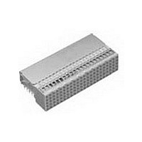
352152-1
Manufacturer Part Number
352152-1
Description
Conn Hard Metric RCP 110 POS 2mm Solder RA Thru-Hole
Manufacturer
TE Connectivity
Type
Hard Metricr
Specifications of 352152-1
Pitch
2 mm
Number Of Rows
5
Number Of Contacts
110
Termination Method
Solder
Mounting
Through Hole
Contact Plating
Gold Over Nickel
Pitch (mm)
2mm
Gender
RCP
Body Orientation
Right Angle
Number Of Contact Rows
5
Mounting Style
Through Hole
Contact Resistance Max
20mOhm
Voltage Rating Max
500VAC
Current Rating (max)
1.5/ContactA
Operating Temp Range
-55C to 125C
Contact Material
Phosphor Bronze
Housing Color
Gray
Housing Material
Polyester
Product Height (mm)
11.4mm
Product Depth (mm)
21mm
Product Length (mm)
43.9mm
Connector Style
B
Number Of Signal Contacts
125
Size
1.732"
Mounting Type
PCB
Connector Polarization
None
Connector Type
Hard Metric (HM)
Rohs Compliant
Yes
Number Of Positions / Contacts
110
Termination Style
Solder Pin
Product Type
Connector
Pcb Mounting Orientation
Right Angle
Board Mount
Free Board
Module Length (mm [in])
44.00 [1.732]
Crosstalk Version
Standard
Shield Type
Ground Return Shielding
Shield Style
Upper
Shielded
Yes
Interface Type
2mm HM
Termination End Plating
Tin-Lead over Nickel
Number Of Positions
110
Grounding Contact
Without
Rows Loaded
A, B, E, D, C
Compactpci Designation
J2, J5
Contact Configuration
ACTION PIN Post, Signal
Feedthrough Post Length (mm [in])
3.30 [0.130]
Compactpci
Yes
Contact Plating, Mating Area, Material
Gold (30)
Contact Base Material
Phosphor Bronze
Mating Alignment
Without
Ul Flammability Rating
UL 94V-0
Rohs/elv Compliance
RoHS compliant, ELV compliant
Lead Free Solder Processes
Not relevant for lead free process
Rohs/elv Compliance History
Always was RoHS compliant
Lead Free Status / RoHS Status
Compliant
Lead Free Status / RoHS Status
Compliant
Available stocks
Company
Part Number
Manufacturer
Quantity
Price


Product Dimensions
Typical Electrical Properties
Flexible Pin Assignment for
Differential Pair
(AA)S — G = 1:1 Across the Column
Suitable for Data Rate — 2.5 Gb/s and
up
Near End Noise — 3.4%
Far End Noise — 1.4%
(BB) S — G = 1:1 in Column
Suitable for Data Rate — 2.5 Gb/s and
up
Near End Noise — 1.8%
Far End Noise — < 1%
(CC) S — G = 3:1
Suitable for Data Rate — 1.5 Gb/s
Near End Noise — 6.4%
Far End Noise — < 1%
Flexible Pin Assignment for
Single Ended
S — G = 1:1
Frequency — 200MHz (Max 400 Mb/s)
Near End Noise — 4.0%
Far End Noise — 1.2%
Technical Documents
Focus on Global Standards
Consortium
Base Station
OBSAI (Open Base Station Architecture
Initiative) Established in Oct/02: http://
www.obsai.org/index.asp)Nokia/
Samsung/LG/Hyundai/Syscom/ZTE
E-PON (Ethernet Passive Optical
Network)
Not Standards yet but some Ad-hoc
level working group in IEEE802.3
http://www.ieee802.org/3/efm/baseline/
index.html
Catalog 65911
Revised 7-05
www.tycoelectronics.com
—Max. Noise at 100ps Edge Rate
—Max. Noise at 500ps Edge Rate
Dimensions are in millimeters
and inches unless otherwise
specified. Values in brackets
are standard equivalents.
AMP Z-PACK 2mm HM Hard Metric
Interconnection System
4 & 4+1 Row Slim Connectors
Vertical Header
[1.890]
Right Angle Receptacle
48.00
25
[.079]
2.00
[.157]
4.00
Connector Assembly
Exemplary Loaded
13.45
[.530
13.40
[.528
Edge of PC Board
+ 0.00
– 0.10
+ .000
– .004
reference purposes only.
.004
Dimensions are shown for
Specifications subject
to change.
[.079]
0.10
[.079]
2.00
2.00
]
48.00 [1.890]
]
48.00 [1.890]
[1.965]
25
24 x 2.00 =
12 x 4.00 =
49.90
1
z a b c d f
d
c
b
a
Recommended PC Board Thickness 1.60
f
25
Max.
d
b
a
[1.965
f
c
z
[.315]
49.90
8.00
1
Recommended PCB Hole Layout
Recommended PCB Hole Layout
+ 0.00
– 0.10
+ .000
– .004
Component Side Shown
Component Side Shown
(Continued)
]
USA: 1-800-522-6752
Canada: 1-905-470-4425
Mexico: 01-800-733-8926
C. America: 52-55-5-729-0425
48.00 [1.890]
[.146]
[.146]
24 x 2.00 =
A
48.00 [1.890]
48.00 [1.890]
3.70
3.70
11
12 x 4.00 =
24 x 2.00 =
A
Action
Action
Area
Area
Pin
Pin
1
Ref.
Ref.
[.037]
0.95
15
Contact Area
11.85
[.467]
Contact Dimensions
Shield
Max.
[.063]
1.60
[.370]
9.40
11.20
[.441
Ref. Line
Seating Plane Connector
[.346]
8.80
Contact Area
0.16
[.348]
25
8.85
Connector
6.00 [.236]
3 x 2.00 =
[.028]
0.70
+ 0.10
– 0.20
+ .004
– .008
[.063
4 x 2.00 =
8.00 [.315]
]
[.323
8.20
Contact
Area
10.80
[.425]
South America: 55-11-3611-1514
Hong Kong: 852-2735-1628
Japan: 81-44-844-8013
UK: 44-141-810-8967
[.002]
Section A-A
.006
0.05
1
+ 0.10
– 0.20
+ .004
– .008
Contact
d c b a
Area
[.370]
]
9.40
[.059]
1.50
All Holes
]
19.00
[.748]
3 x 2.00 =
6.00 [.236]
[.079]
2.00
10
11
12
13
14
15
16
17
18
19
20
21
22
23
24
25
1
2
3
4
5
6
7
8
9
d
c
b
a
f
Contact Layout
[.002]
[.378]
[.115]
0.05
Action Pin
9.60
2.93
z a b c d f
Area
8.00 [.315]
[.067]
4 x 2.00 =
1.70
[.067]
1.70
All Holes
Ref.
[.130]
3.30
Ref.
23
Related parts for 352152-1
Image
Part Number
Description
Manufacturer
Datasheet
Request
R

Part Number:
Description:
Conn Hard Metric F 110 POS 2mm Press Fit RA Thru-Hole
Manufacturer:
TE Connectivity
Datasheet:


Part Number:
Description:
Printers THERMAL PRINTER HS-SLEEVE MARKER
Manufacturer:
TE Connectivity


Part Number:
Description:
High Speed / Modular Connectors 30P HEADER ASSY
Manufacturer:
TE Connectivity
Datasheet:

Part Number:
Description:
High Speed / Modular Connectors REC 6X005P R/A LT B-PLANE HS3
Manufacturer:
TE Connectivity
Datasheet:

Part Number:
Description:
High Speed / Modular Connectors 2MM HM RCPT 50P R/A AU
Manufacturer:
TE Connectivity
Datasheet:

Part Number:
Description:
High Speed / Modular Connectors 2MM HM RCPT 50P R/A AU
Manufacturer:
TE Connectivity
Datasheet:


Part Number:
Description:
352=FUSE BLK SECTION T CLAMP
Manufacturer:
TE Connectivity
Datasheet:

Part Number:
Description:
Manufacturer:
TE Connectivity
Datasheet:


Part Number:
Description:
Manufacturer:
TE Connectivity
Datasheet:

Part Number:
Description:
Manufacturer:
TE Connectivity
Datasheet: