352152-1 TE Connectivity, 352152-1 Datasheet - Page 65
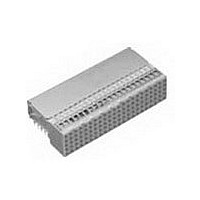
352152-1
Manufacturer Part Number
352152-1
Description
Conn Hard Metric RCP 110 POS 2mm Solder RA Thru-Hole
Manufacturer
TE Connectivity
Type
Hard Metricr
Specifications of 352152-1
Pitch
2 mm
Number Of Rows
5
Number Of Contacts
110
Termination Method
Solder
Mounting
Through Hole
Contact Plating
Gold Over Nickel
Pitch (mm)
2mm
Gender
RCP
Body Orientation
Right Angle
Number Of Contact Rows
5
Mounting Style
Through Hole
Contact Resistance Max
20mOhm
Voltage Rating Max
500VAC
Current Rating (max)
1.5/ContactA
Operating Temp Range
-55C to 125C
Contact Material
Phosphor Bronze
Housing Color
Gray
Housing Material
Polyester
Product Height (mm)
11.4mm
Product Depth (mm)
21mm
Product Length (mm)
43.9mm
Connector Style
B
Number Of Signal Contacts
125
Size
1.732"
Mounting Type
PCB
Connector Polarization
None
Connector Type
Hard Metric (HM)
Rohs Compliant
Yes
Number Of Positions / Contacts
110
Termination Style
Solder Pin
Product Type
Connector
Pcb Mounting Orientation
Right Angle
Board Mount
Free Board
Module Length (mm [in])
44.00 [1.732]
Crosstalk Version
Standard
Shield Type
Ground Return Shielding
Shield Style
Upper
Shielded
Yes
Interface Type
2mm HM
Termination End Plating
Tin-Lead over Nickel
Number Of Positions
110
Grounding Contact
Without
Rows Loaded
A, B, E, D, C
Compactpci Designation
J2, J5
Contact Configuration
ACTION PIN Post, Signal
Feedthrough Post Length (mm [in])
3.30 [0.130]
Compactpci
Yes
Contact Plating, Mating Area, Material
Gold (30)
Contact Base Material
Phosphor Bronze
Mating Alignment
Without
Ul Flammability Rating
UL 94V-0
Rohs/elv Compliance
RoHS compliant, ELV compliant
Lead Free Solder Processes
Not relevant for lead free process
Rohs/elv Compliance History
Always was RoHS compliant
Lead Free Status / RoHS Status
Compliant
Lead Free Status / RoHS Status
Compliant
Available stocks
Company
Part Number
Manufacturer
Quantity
Price


Coordination dimensions
and tolerances
The accompanying diagrams show the
depth dimensions used in the equip-
ment practice, used for both 2 and 2.5
[.079 and .098] systems, and allowable
tolerances for subrack and backplane
bending.
Coordination Dimension M
As defined in the DIN 43356 and IEEE
1301 Hard Metric equipment practices
for the 2.5mm system, and used in IEC
61076-4-101, the dimension M
range for free board engagement with
the backplane.
The specified contact mating must be
maintained on a mated pair of connectors,
within the range of M = 14 to 16.5 [.551
to .650] for the shortest mating level 1.
For mating levels 2 and 3 the contact
ranges are 14 to 18 [.551 to .709] and
14 to 19.5 [.551 to .768].
See page 67 for further details on
AMP Z-PACK 2mm HM contact mating
levels.
Misalignment and inclination
tolerances
Guiding and polarizing lugs of Type A,
M and L connectors, also at ends of
Type C and N, allow the mating
tolerances shown here.
Tolerances apply only when guide lugs
are separated by only one Type B
module without lugs.
Catalog 65911
Revised 7-05
www.tycoelectronics.com
ref
Dimensions are in millimeters
and inches unless otherwise
specified. Values in brackets
are standard equivalents.
is the
ref
[.295]
AMP Z-PACK 2mm HM Hard Metric
Interconnection System
Page_Head
Dimensions and Tolerances
[.299]
[.291]
7.5
7.6
7.4
Transverse & Longitudinal Axes
Allowed Misalignment,
153.5 [6.043]
153.5 [6.043]
153.5 [6.043]
[.098]
± 2.5
175.5 [6.909]
[.079]
176.5 [6.949]
± 2.0
(Continued)
175.0 [6.890]
reference purposes only.
Dimensions are shown for
Specifications subject
to change.
[.551]
14.0
[.551]
[.492]
[.567]
14.4
14.0
[.614]
12.5
[.650]
15.6
[.059]
16.5
1.5
Guiding &
Polarizing
Lugs
M
M
M
M
ref
0.4 [.016]
ref
M
ref
ref
ref
USA: 1-800-522-6752
Canada: 1-905-470-4425
Mexico: 01-800-733-8926
C. America: 52-55-5-729-0425
Coordination Dimensions
Subrack tolerances
Worst case condition 1
without back panel bending
Worst case condition 1
with back panel bending
Subrack tolerances
Worst case condition 2
without back panel bending
Worst case condition 2
with back panel bending
0.9 [.035]
Transverse & Longitudinal Axes
Allowed Inclination,
[.124]
[.108]
3.15
Mismatch
2.75
Mismatch
Max.
Max.
223957 Female Guide Module
223957 Female Guide Module
South America: 55-11-3611-1514
Hong Kong: 852-2735-1628
Japan: 81-44-844-8013
UK: 44-141-810-8967
223982 Guide Pin with
223956 Guide Pin with
± 2˚
± 2˚
65
Related parts for 352152-1
Image
Part Number
Description
Manufacturer
Datasheet
Request
R

Part Number:
Description:
Conn Hard Metric F 110 POS 2mm Press Fit RA Thru-Hole
Manufacturer:
TE Connectivity
Datasheet:


Part Number:
Description:
Printers THERMAL PRINTER HS-SLEEVE MARKER
Manufacturer:
TE Connectivity


Part Number:
Description:
High Speed / Modular Connectors 30P HEADER ASSY
Manufacturer:
TE Connectivity
Datasheet:

Part Number:
Description:
High Speed / Modular Connectors REC 6X005P R/A LT B-PLANE HS3
Manufacturer:
TE Connectivity
Datasheet:

Part Number:
Description:
High Speed / Modular Connectors 2MM HM RCPT 50P R/A AU
Manufacturer:
TE Connectivity
Datasheet:

Part Number:
Description:
High Speed / Modular Connectors 2MM HM RCPT 50P R/A AU
Manufacturer:
TE Connectivity
Datasheet:


Part Number:
Description:
352=FUSE BLK SECTION T CLAMP
Manufacturer:
TE Connectivity
Datasheet:

Part Number:
Description:
Manufacturer:
TE Connectivity
Datasheet:


Part Number:
Description:
Manufacturer:
TE Connectivity
Datasheet:

Part Number:
Description:
Manufacturer:
TE Connectivity
Datasheet: