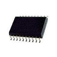
PCKEP14PW-T NXP Semiconductors, PCKEP14PW-T Datasheet - Page 5

PCKEP14PW-T
Manufacturer Part Number
PCKEP14PW-T
Description
Clock Synthesizer / Jitter Cleaner 2.5/3.3V PECL/ECL 1:5 CLK DRV
Manufacturer
NXP Semiconductors
Type
Clock Driverr
Datasheet
1.PCKEP14PW112.pdf
(15 pages)
Specifications of PCKEP14PW-T
Number Of Clock Inputs
2
Mode Of Operation
Differential
Output Frequency
>2000MHz
Output Logic Level
ECL/PECL
Operating Supply Voltage (min)
-2.375/2.375V
Operating Supply Voltage (typ)
-2.5/-3.3/2.5/3.3V
Operating Supply Voltage (max)
-3.8/3.8V
Package Type
TSSOP
Operating Temp Range
-40C to 85C
Operating Temperature Classification
Industrial
Signal Type
ECL/HSTL/LVDS/PECL
Mounting
Surface Mount
Pin Count
20
Mounting Style
SMD/SMT
Package / Case
TSSOP-20
Lead Free Status / RoHS Status
Compliant
Other names
PCKEP14PW,118
Philips Semiconductors
8. Limiting values
Table 5:
In accordance with the Absolute Maximum Rating System (IEC 60134).
9. Static characteristics
Table 6:
V
[1]
[2]
[3]
[4]
9397 750 09565
Product data
Symbol
V
V
V
I
I
T
T
R
R
T
Symbol
I
V
V
V
V
V
I
I
V
out
BB
EE
IH
IL
CC
amb
stg
sld
CC
EE
I
OH
OL
IH
IL
IHCMR
BB
th(j-a)
th(j-c)
= 2.5 V; V
Devices are designed to meet the DC specifications shown in this table, after thermal equilibrium has been established. The circuit is in
a test socket or mounted on a printed circuit board and transverse air flow greater than 500 LFPM is maintained.
Input and output parameters vary 1:1 with V
All loading with 50
V
differential input signal.
IHCMR(min)
Parameter
power supply current
HIGH-level output
voltage
LOW-level output voltage
HIGH-level input voltage single-ended
LOW-level input voltage
HIGH-level input voltage,
common mode range
(differential)
HIGH-level input current
LOW-level input current
output reference voltage
Parameter
PECL mode power supply
NECL mode power supply
PECL mode input voltage
NECL mode input voltage
output current
V
operating ambient temperature
storage temperature range
thermal resistance from junction to ambient
thermal resistance from junction to case
soldering temperature
Limiting values
PECL DC characteristics
BB
EE
varies 1:1 with V
source current
= 0 V
[2]
to V
CC
EE
2 V.
, V
IHCMR(max)
Conditions
single-ended
CLK
CLK
[1]
varies 1:1 with V
CC
. V
EE
Rev. 01 — 30 October 2002
can vary +0.125 V to 1.3 V.
[3]
[3]
[4]
45
1355 1480 1605 1355 1500 1605 1355 1510 1605 mV
555
1335 -
555
1.2
-
0.5
1075 1165 1265 1065 1165 1265 1085 1180 1270 mV
Min
150 -
CC
2.5 V/3.3 V 1:5 differential ECL/PECL/HSTL clock driver
T
amb
. The V
Conditions
V
V
V
V
continuous
surge
0 LFPM
500 LFPM
EE
CC
EE
CC
60
720
-
-
-
-
Typ
= 40 C
= 0 V
= 0 V; V
= 0 V
= 0 V; V
IHCMR
75
805
1620 1335 -
875
2.5
150
-
-
Max
range is referenced to the most positive side of the
I
I
V
45
555
555
1.2
-
0.5
V
Min
150 -
CC
EE
T
amb
60
700
-
-
-
-
Typ
= +25 C
© Koninklijke Philips Electronics N.V. 2002. All rights reserved.
75
805
1620 1275 -
875
2.5
150
-
-
Max
Min
-
-
-
-
-
-
0
-
-
23
-
40
65
45
555
555
1.2
-
0.5
Min
150 -
T
PCKEP14
amb
Max
4.1
4.1
50
100
0.1
+85
+150
140
100
41
265
60
710
-
-
-
-
4.1
4.1
Typ
= +85 C
75
805
1620 mV
875
2.5
150
-
-
Max
Unit
V
V
V
V
mA
mA
mA
C
C
C/W
C/W
C/W
C
5 of 15
Unit
mA
mV
mV
V
A
A
A


