104130-5 TE Connectivity, 104130-5 Datasheet - Page 265
104130-5
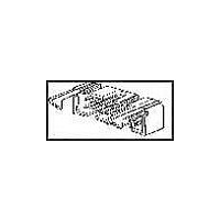
Manufacturer Part Number
104130-5
Description
Conn Ejector Header HDR 26 POS 2.54mm Solder RA Thru-Hole
Manufacturer
TE Connectivity
Type
Ejector Headerr
Series
AMP-LATCHr
Datasheet
1.1-102618-8.pdf
(320 pages)
Specifications of 104130-5
Pitch
2.54 mm
Number Of Rows
2
Number Of Contacts
26
Gender
HDR
Contact Plating
Gold Over Nickel
Termination Method
Solder
Connector Type
Wire To Board
Contact Termination
Right Angle Through Hole
No. Of Contacts
26
No. Of Rows
2
Pitch Spacing
2.54mm
Rohs Compliant
No
Product Line
AMP-LATCH
Profile
Low
Pcb Mounting Orientation
Right Angle
Pcb Mount Retention
Without
Mating Connector Lock
Without
Housing Style
4-Sided
Ejection Latches
With
Post Size (mm [in])
0.64 [.025]
Shrouded
Yes
[shrouded] End Dimension (mm [in])
3.81 [0.150]
Current Rating (a)
1
Insulation Resistance (m?)
5,000
Termination Post Length (mm [in])
3.43 [0.135]
Solder Tail Contact Plating
Tin-Lead over Nickel
Header Type
Pin Header
Number Of Positions
26
Centerline, Matrix (mm [in])
2.54 x 2.54 [.100 x .100]
Daisy Chain
With
Preloaded
Yes
Contact Plating, Mating Area, Material
Gold (30), Gold Flash over Palladium Nickel
Contact Shape
Square
Contact Base Material
Copper Alloy
Connector Style
Header - Pin
Mating Alignment Type
Center, Dual Polarizing Bar
Mating Alignment
With
Housing Material
Thermoplastic - GF
Ul Flammability Rating
UL 94V-0
Housing Color
Black
Rohs/elv Compliance
Not ELV/RoHS compliant
Lead Free Solder Processes
Not suitable for lead free processing
Approved Standards
UL E28476, CSA LR7189
Operating Temperature (°c)
-65 – +105
Temperature Rating
Standard


Insulation Displacement
Contacts
Material and Finish
Copper alloy, duplex plated .000030
[0.00076] gold in mating area, .000100-
.000200 [0.00254-0.00508] tin in crimp
area, with entire contact underplated
.000050 [0.00127] nickel
Related Product Data
Performance Characteristics —
page 255
Application Tooling —
pages 273-275
Technical Documents
pages 277, 278
Product Specification
108-25015, 108-25018, 108-25030
Application Specification
114-25032
Instruction Sheet
408-6532
Catalog 1307819
Revised 8-08
www.tycoelectronics.com
—
are metric equivalents.
Dimensions are in inches and
millimeters unless otherwise
specified. Values in brackets
AMPMODU Interconnection System
Replacement MT Receptacle Contacts
Note: Termination tooling for MT receptacle insulation displacement contacts is shown on pages 273-275.
MT receptacle contacts
incorporate the following
features.
Note: All part numbers are RoHS compliant.
overstress
30-26
26-22
22-20
AWG
Anti-
Wire Size Range
0.05-0.15
0.12-0.3
0.3-0.6
Dimensions are shown for
reference purposes only.
Specifications subject
to change.
[mm
Misalignment
Cantilever
Tolerance
2
Beams
]
Wide
[1.27]
.050
Insulation
Diameter
Contact Ident.
The MT receptacle contact
cross-section is primarily
rectangular, with rounded
corners. Two integral
cantilever beams contact
the mating square male
posts. Deflection of these
spring members is limited
by anti-overstress and
excessive permanent
deformation is prevented.
This feature allows a wide
range for tolerance of
misalignment of mating
contacts.
Max.
1
2
3
Standard Pressure
Receptacle
USA: 1-800-522-6752
Canada: 1-905-470-4425
Mexico: 01-800-733-8926
C. America: 52-55-1106-0803
5-102395-2
5-102399-1
5-102449-6
Part No.
Identification
Contact
The configuration of the
receptacle completely
encloses the spring
members helping to prevent
damage during handling
and assembly, and makes
the system compatible with
automatic application
techniques.
Contact Ident.
Extraction/Lance Reset Tool
South America: 55-11-2103-6000
Hong Kong: 852-2735-1628
Japan: 81-44-844-8013
UK: 44-8706-080-208
—
4
5
High Pressure
No. 843477-3
Receptacle
5-102641-6
5-102642-6
Part No.
—
265
5
Related parts for 104130-5
Image
Part Number
Description
Manufacturer
Datasheet
Request
R

Part Number:
Description:
Conn Ejector Header HDR 10 POS 2.54mm Solder RA Thru-Hole
Manufacturer:
TE Connectivity
Datasheet:

Part Number:
Description:
Conn Ejector Header HDR 16 POS 2.54mm Solder RA Thru-Hole
Manufacturer:
TE Connectivity
Datasheet:
Part Number:
Description:
Conn Ejector Header HDR 20 POS 2.54mm Solder RA Thru-Hole
Manufacturer:
TE Connectivity
Datasheet:
Part Number:
Description:
WIRE-BOARD CONN, HEADER, 14POS, 2.54MM
Manufacturer:
TE Connectivity
Datasheet:
Part Number:
Description:
WIRE-BOARD CONN, HEADER, 34POS, 2.54MM
Manufacturer:
TE Connectivity

Part Number:
Description:
High Speed / Modular Connectors 30P HEADER ASSY
Manufacturer:
TE Connectivity
Datasheet:

Part Number:
Description:
High Speed / Modular Connectors REC 6X005P R/A LT B-PLANE HS3
Manufacturer:
TE Connectivity
Datasheet:

Part Number:
Description:
High Speed / Modular Connectors 2MM HM RCPT 50P R/A AU
Manufacturer:
TE Connectivity
Datasheet:

Part Number:
Description:
High Speed / Modular Connectors 2MM HM RCPT 50P R/A AU
Manufacturer:
TE Connectivity
Datasheet:


Part Number:
Description:
Manufacturer:
TE Connectivity
Datasheet:


Part Number:
Description:
Manufacturer:
TE Connectivity
Datasheet:

Part Number:
Description:
Manufacturer:
TE Connectivity
Datasheet:

Part Number:
Description:
Manufacturer:
TE Connectivity
Datasheet: