579302B00000G Aavid Thermalloy, 579302B00000G Datasheet - Page 9
579302B00000G
Manufacturer Part Number
579302B00000G
Description
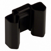
HEATSINK TO-220 SNAP-DOWN .75"
Manufacturer
Aavid Thermalloy
Datasheet
1.T405R..pdf
(116 pages)
Specifications of 579302B00000G
Package Cooled
TO-220
Attachment Method
Clip
Outline
24.89mm x 19.05mm
Height
0.440" (11.18mm)
Power Dissipation @ Temperature Rise
3W @ 50°C
Thermal Resistance @ Forced Air Flow
6°C/W @ 500 LFM
Thermal Resistance @ Natural
16.8°C/W
Product
Heatsinks
Fin Style
Two Side Fins
Thermal Resistance
16.8 C / W
Dimensions
19.05 mm L x 24.89 mm W x 11.18 mm H
Designed For
TO-220
Color
Black
Packages Cooled
TO-220
External Width - Metric
24.89mm
External Height - Metric
11.18mm
External Length - Metric
19.05mm
Width
24.89mm
Length
19.05mm
Rohs Compliant
Yes
External Width - Imperial
0.98"
External Height - Imperial
0.44"
External Length - Imperial
0.75"
Lead Free Status / RoHS Status
Lead free / RoHS Compliant
Other names
002636
579302B00000
HS220
579302B00000
HS220
Available stocks
Company
Part Number
Manufacturer
Quantity
Price
Company:

Part Number:
579302B00000G
Manufacturer:
ATH
Quantity:
33 546


The basic equation for heat transfer or power dissipation may be stated as follows:
Where:
P D = the power dissipated by the semiconductor device in watts.
ΔT = the temperature difference of driving potential which causes the flow of heat.
ΣR θ = the sum of the thermal resistances of the heat flow path across which ΔT exists.
The above relationship may be stated in the following forms:
The above equations are generally used to determine the required thermal resistance of the heat sink (R θSA ),
since the heat dissipation, maximum junction and/or case temperature, and ambient temperature are known or set.
Figure 1 indicates the location of the various heat
flow paths, temperatures and thermal resistances.
FIGURE 1
Where:
T J = the junction temperature in °C (maximum is usually stated by the manufacturer of the semiconductor device).
T C = case temperature of the semiconductor device in °C.
T S = temperature of the heat sink mounting surface in thermal contact with the semiconductor device in °C.
T A = ambient air temperature in °C.
How to select a heat sink
P D =
R θJC = thermal resistance from junction to case of the semiconductor device in °C per watt
R θCS = thermal resistance through the interface between the semiconductor device
R θSA = thermal resistance from mounting surface to ambient or thermal resistance of heat sink in °C per watt.
P D =
Semiconductor case
www.aavidthermalloy.com
R θJC + R θCS + R θSA
(cooler/dissipator)
Mounting surface
(usually stated by manufacturer of semiconductor device).
(heat source)
and the surface on which it is mounted in °C per watt.
Δ T
ΣR θ
Junction
Interface
T J –T A
P
R
D
θJC
R
θCS
T
J
T
C
T
S
surface to ambient, equation (3)
AMERICA
to ambient, equation (1)
Heat flow path junction
to ambient equation (2)
EUROPE
Heat flow path mounting
Heat flow path case
R
θSA
Italy Tel: +39 051 764011 email: sales.it@aavid.com
United Kingdom Tel: +44 1793 401400 email: sales.uk@aavid.com
USA Tel: +1 (603) 224-9988 email: info@aavid.com
P D =
P
D
Atmosphere
R θCS + R θSA
or ambient
T
T
T C –T A
A
A
The common practice is to represent the system with
a network of resistances in series as shown in Figure 2.
FIGURE 2
T J
R θJC
ASIA
P D =
How To Select a Heat Sink
Singapore Tel: +65 6362 8388 email: sales@aavid.com.sg
Taiwan Tel: +886(2) 2698-9888 email: sales@aavid.com.tw
T S –T A
T C
R θSA
R θCS
T S
R θSA
T A
9
Related parts for 579302B00000G
Image
Part Number
Description
Manufacturer
Datasheet
Request
R

Part Number:
Description:
Heatsink black, extrusion+Pins; 38mm cut;
Manufacturer:
Aavid Thermalloy
Part Number:
Description:
Heatsink extrusion;custom L:150mm;27x50mm;black;
Manufacturer:
Aavid Thermalloy
Part Number:
Description:
Heatsink custom 0S507 extrusion profile cut to length 100mm, black anodi
Manufacturer:
Aavid Thermalloy
Part Number:
Description:
Heatsink custom cut 80mm;black anodized; WxH:30x47.2mm; w/o pad
Manufacturer:
Aavid Thermalloy
Part Number:
Description:
Heatsink extrusion;custom L:100mm;39x31.50mm;black;
Manufacturer:
Aavid Thermalloy
Part Number:
Description:
Heatsink custom 0S515 extrusion cut to length 100mm, black anodise
Manufacturer:
Aavid Thermalloy
Part Number:
Description:
Heatsink extrusion;custom L:100mm;40x75mm;black;
Manufacturer:
Aavid Thermalloy
Part Number:
Description:
Heatsink extrusion;custom L:50mm;40x75mm;black;
Manufacturer:
Aavid Thermalloy
Part Number:
Description:
Heatsink extrusion;custom L:100mm;black;
Manufacturer:
Aavid Thermalloy
Part Number:
Description:
Heatsink extrusion;custom L:150mm;black;
Manufacturer:
Aavid Thermalloy
Part Number:
Description:
Heatsink extrusion;custom L:50mm;black;
Manufacturer:
Aavid Thermalloy
Part Number:
Description:
Heatsink extrusion;custom L:100mm;27x60mm black;
Manufacturer:
Aavid Thermalloy
Part Number:
Description:
Heatsink extrusion;custom L:50mm;27x60mm black;
Manufacturer:
Aavid Thermalloy
Part Number:
Description:
Heatsink extrusion;custom L:150mm;49.50x85.50mm black;
Manufacturer:
Aavid Thermalloy