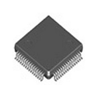
IDT77V106L25TFI IDT, Integrated Device Technology Inc, IDT77V106L25TFI Datasheet - Page 19

IDT77V106L25TFI
Manufacturer Part Number
IDT77V106L25TFI
Description
Manufacturer
IDT, Integrated Device Technology Inc
Datasheet
1.IDT77V106L25TFI.pdf
(27 pages)
Specifications of IDT77V106L25TFI
Data Rate
25.6/51.2Mbps
Number Of Channels
1
Type Of Atm Phy Interface
UTOPIA
Operating Supply Voltage (typ)
3.3V
Operating Supply Voltage (min)
3V
Operating Supply Voltage (max)
3.6V
Operating Temp Range
-40C to 85C
Operating Temperature Classification
Industrial
Pin Count
64
Mounting
Surface Mount
Lead Free Status / RoHS Status
Not Compliant
Available stocks
Company
Part Number
Manufacturer
Quantity
Price
Company:
Part Number:
IDT77V106L25TFI
Manufacturer:
NEC
Quantity:
4 102
Part Number:
IDT77V106L25TFI
Manufacturer:
IDT
Quantity:
20 000
INTERRUPT STATUS REGISTER
Address: 0x01
DIAGNOSTIC CONTROL REGISTER
Address: 0x02
1, 0
IDT77V106L25
Bit
Bit
7
6
5
4
3
2
7
6
5
4
3
2
1
0
Type
Type
sticky
sticky
sticky
sticky
sticky
sticky
R/W
R/W
R/W
R/W
R/W
R/W
R/W
R
-
0 = Bad Signal Good Signal Bit. See definitions earlier in this data sheet
Initial State
Initial State
0 = UTOPIA
0 = High-Z
0 = normal
0 = normal
0 = normal
0 = normal
0 = normal
0
0
0
0
0
0
0
Force TxCLAV Deassert
This feature can be used during line loopback mode to prevent cells from being passed across the Utopia bus for
transmission.
RxCLAV Operation Select
The UTOPIA standard dictates that during cell mode operation, if the receive FIFO no longer has a complete cell
available for transfer from PHY, RxCLAV is deasserted following transfer of the last byte out of the PHY
to the upstream system. With this bit set, early deassertion of this signal will occur coincident with the end of Payload
byte 44 (as in octet mode for TxCLAV). This provides early indication to the upstream system of this impending
condition.
Single/Multi-PHY Configuration Select
0 = single
1 = Multi-PHY mode
RFLUSH = Clear Receive FIFO
This signal is used to tell the TC to flush (clear) all data in the receive FIFO. The TC signals this completion by
clearing this bit.
Insert Transmit Payload Error
Tells TC to insert cell payload errors in transmitted cells. This can be used to test error detection and recovery
systems at destination station, or, under loopback control, at the local receiving station. This payload error is
accomplished by flipping bit 0 of the last cell payload byte.
Insert Transmit HEC Error
Tells TC to insert HEC error in Byte 5 of transmitted cells. This can be used to test error detection and recovery
systems in downstream switches, or, under loopback control, the local receiving station. The HEC error is
accomplished by flipping bit 0 of the HEC byte.
Loopback Control
bit # 1
Reserved
1 - Good Signal
1 - Bad Signal
HEC error cell received. Set when a HEC errors detected on received cell.
"Short Cel" Received
Interrupt signal which flags received cells with fewer than 53 bytes. This condition is detected when receiving
Start-of-Cell command bytes with fewer than 53 bytes between them"
Transmit Parity Error
If Bit 4 of the Master Control Register (Transmit Data Parity Check) is set, this interrupt flags a transmit data parity
error condition. Odd parity is used.
Receive Signal Condition Change. This interrupt is set when the received "signal" changes either from "bad to good"
from "good to bad".
Received Symbol Error. Set when an undefined 5-bit symbol is received.
Receive FIFO Overflow. Interrupt which indicates when the receive FIFO has filled and cannot accept additional data.
0 = "Standard UTOPIA RxCLAV"
1 = "Cell mode = Byte mode"
0 0 Normal mode (receive from network)
1 1 PHY Loopback
1 1 Line Loopback
0
Never High-Z RxDAY+TA, RxPARITY, and RxSOC
High-Z RxDATA, RxPARITY, and RxSOC when RxEN = 1
19
Function
Function


