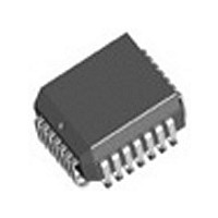
IDT82V1671J IDT, Integrated Device Technology Inc, IDT82V1671J Datasheet - Page 66

IDT82V1671J
Manufacturer Part Number
IDT82V1671J
Description
Manufacturer
IDT, Integrated Device Technology Inc
Datasheet
1.IDT82V1671J.pdf
(107 pages)
Specifications of IDT82V1671J
Number Of Channels
4
On-hook Transmission
Yes
Polarity Reversal
Yes
On-chip Ring Relay Driver
Yes
Operating Supply Voltage (typ)
3.3V
Operating Temp Range
-40C to 85C
Package Type
PLCC
Operating Temperature Classification
Industrial
Pin Count
28
Mounting
Surface Mount
Operating Current
95mA
Operating Supply Voltage (max)
3.465V
Operating Supply Voltage (min)
3.135V
Lead Free Status / RoHS Status
Not Compliant
Available stocks
Company
Part Number
Manufacturer
Quantity
Price
Company:
Part Number:
IDT82V1671J
Manufacturer:
BROADCOM
Quantity:
457
Part Number:
IDT82V1671J
Manufacturer:
IDT
Quantity:
20 000
RSLIC & CODEC CHIPSET
GREG4: Master Clock Selection and Channel Program Enable, Read/Write (23H/A3H)
GREG5: Hardware and Software Reset, Write (A4H); Version Number, Read (24H)
CH_EN[3:0]
MCLK_SEL[3:0] Select the frequency of the master clock. In MPI mode, there are nine frequencies can be selected as the master
When write this register, a hardware or a software reset will be applied as described below:
HW_RST
SW_RST
RCH_SEL[3:0] Select channel(s) for software reset. The RCH_SEL[3:0] bits select the local registers of Channel 4 to Channel 1,
Command
Command
I/O data
I/O data
HW_RST
Hardware reset of the CODEC. The action of this hardware reset is equivalent to pulling the RESET pin of the CODEC
low.
HW_RST = 0:
HW_RST = 1:
Software reset of the CODEC. This software reset operation resets those local registers specified by the RCH_SEL[3:0]
bits, but the Coe-RAM is not affected.
SW_RST = 0:
SW_RST = 1:
respectively, to be reset.
RCH_SEL[3] = 0: The local registers of Channel 4 will not be reset after executing a software reset command (default));
RCH_SEL[3] = 1: The local registers of Channel 4 will be reset after executing a software reset command;
Channel programming enable. In MPI mode, the channel programming enable command is used to specify the
channel(s) to which the subsequent local command or Coe-RAM command will be applied. The CH_EN[3:0] bits
enable Channel 4 to Channel 1 for programming, respectively. The CH_EN[3:0] bits are used for MPI mode only.
CH_EN[3] = 0:
CH_EN[3] = 1:
CH_EN[2] = 0:
CH_EN[2] = 1:
CH_EN[1] = 0:
CH_EN[1] = 1:
CH_EN[0] = 0:
CH_EN[0] = 1:
clock. The MCLK_SEL[3:0] bits are used for MPI mode only.
(In GCI mode, the frequency of the master clock is either 2.048 MHz or 4.096 MHz, the same as the frequency of Data
Clock (DCL). The internal circuit of the CODEC monitors the DCL input to determine which frequency is being used.)
MCLK_SEL[3:0] = 0000:
MCLK_SEL[3:0] = 0001:
MCLK_SEL[3:0] = 0010:
MCLK_SEL[3:0] = 0110:
MCLK_SEL[3:0] = 1110:
MCLK_SEL[3:0] = 0101:
MCLK_SEL[3:0] = 1101:
MCLK_SEL[3:0] = 0100:
MCLK_SEL[3:0] = 1100:
R/W
R/W
b7
b7
Reserved
b6
b6
0
0
No software reset signal will be generated (default);
A software reset signal will be generated. If the SW_RST bit is set to 1, those local registers specified
by the RCH_SEL[3:0] bits will be reset, but other local registers and all the global registers as well as
the Coe-RAM will not be affected.
CH_EN[3:0]
Disabled, Channel 4 can not receive Local Commands and Coe-RAM Commands (default);
Enabled, Channel 4 can receive Local Commands and Coe-RAM Commands;
Disabled, Channel 3 can not receive Local Commands and Coe-RAM Commands (default);
Enabled, Channel 3 can receive Local Commands and Coe-RAM Commands;
Disabled, Channel 2 can not receive Local Commands and Coe-RAM Commands (default);
Enabled, Channel 2 can receive Local Commands and Coe-RAM Commands;
Disabled, Channel 1 can not receive Local Commands and Coe-RAM Commands (default);
Enabled, Channel 1 can receive Local Commands and Coe-RAM Commands;
No hardware reset signal will be generated (default);
A hardware reset signal will be generated.
SW_RST
8.192 MHz
4.096 MHz
2.048 MHz (default)
1.536 MHz
1.544 MHz
3.072 MHz
3.088 MHz
6.144 MHz
6.176 MHz
b5
b5
1
1
Reserved
66
b4
b4
0
0
RCH_SEL[3] RCH_SEL[2] RCH_SEL[1] RCH_SEL[0]
b3
b3
0
0
b2
b2
0
MCLK_SEL[3:0]
1
IDT82V1671/IDT82V1671A, IDT82V1074
b1
b1
1
0
b0
b0
1
0


