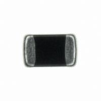
BK2125HM601-T Taiyo Yuden, BK2125HM601-T Datasheet - Page 34

BK2125HM601-T
Manufacturer Part Number
BK2125HM601-T
Description
FERRITE BEAD 600 OHM 0805
Manufacturer
Taiyo Yuden
Series
BKr
Datasheets
1.BK1005LM182-T.pdf
(27 pages)
2.BKP1608HS181-T.pdf
(53 pages)
3.BK2125HM601-T.pdf
(1 pages)
Specifications of BK2125HM601-T
Impedance @ Frequency
600 Ohm @ 100MHz
Current Rating
500mA
Dc Resistance (dcr)
250.0 mOhm Max
Filter Type
Differential Mode - Single
Number Of Lines
1
Package / Case
0805 (2012 Metric)
Mounting Type
Surface Mount
Impedance
600ohm
Ferrite Grade
HM
Dc Resistance Max
0.25ohm
Dc Current Rating
500mA
Ferrite Mounting
SMD
Ferrite Case Style
0805 / 2012
Frequency Max
300MHz
Rohs Compliant
Yes
Features
HM
Frequency
100MHz
Lead Free Status / RoHS Status
Lead free / RoHS Compliant
Other names
587-1902-2
BK2125HM601-T
BK2125HM601-T
Available stocks
Company
Part Number
Manufacturer
Quantity
Price
Company:
Part Number:
BK2125HM601-T
Manufacturer:
Taiyo Yuden
Quantity:
83 606
Company:
Part Number:
BK2125HM601-T
Manufacturer:
Taiyoyuden
Quantity:
4 673
Part Number:
BK2125HM601-T
Manufacturer:
TAIYO/太诱
Quantity:
20 000
Precautions on the use of Multilayer chip Inductors, Multilayer chip inductors for high frequency, Multilayer ferrite chip beads
1. Circuit Design
2. PCB Design
PRECAUTIONS
Stages
◆Verification of operating environment, electrical rating
1. A malfunction in medical equipment, spacecraft, nucle-
◆Operating Current (Verification of Rated current)
1. The operating current for inductors must always be
2. Do not apply current in excess of the rated value
(1) The amount of solder applied can affect the ability
(2) When more than one part is jointly soldered onto
(3) The larger size of land patterns and amount of
◆Pattern configurations
1. When inductors are mounted on a PCB, the size of
(Design of Land-patterns)
and performance
ar reactors, etc. may cause serious harm to human
life or have severe social ramifications. As such, any
inductors to be used in such equipment may require
higher safety and/or reliability considerations and
should be clearly differentiated from components used
in general purpose applications.
lower than their rated values.
because the inductance may be reduced due to the
magnetic saturation effect.
land patterns and the amount of solder used (size
of fillet) can directly affect inductor performance.
Therefore, the following items must be carefully con-
sidered in the design of solder land patterns:
of chips to withstand mechanical stresses which
may lead to breaking or cracking. Therefore, when
designing land-patterns it is necessary to consider
the appropriate size and configuration of the solder
pads which in turn determines the amount of solder
necessary to form the fillets.
the same land or pad, the pad must be designed so
that each component's soldering point is separated
by solder-resist.
solder, the smaller Q value after mounting on PCB.
It makes higher the Q value to design land patterns
smaller than terminal electrode of chips.
Precautions
(1) Recommended land dimensions for a typical chip inductor land patterns
1. The following diagrams and tables show some examples of recommended
Recommended land dimensions for wave-soldering (unit: mm)
Recommended land dimensions for reflow-soldering (unit: mm)
Excess solder can affect the ability of chips to withstand mechanical stresses.
Therefore, please take proper precautions when designing land-patterns.
Type
patterns to prevent excessive solder amounts (larger fillets which extend
above the component end terminations) . Examples of improper pattern
designs are also shown.
for PCBs
Type
A
B
C
B
C
A
W
L
W
L
0.20∼0.30 0.45∼0.55 0.50∼0.55 0.6∼0.8
0.20∼0.30 0.40∼0.50 0.30∼0.40 0.6∼0.8
0.25∼0.40 0.45∼0.55 0.60∼0.70 0.6∼0.8
8
0603
0.6
0.3
0.8∼1.0
0.5∼0.8
0.6∼0.8
1608
1.6
0.8
1005
1.0
0.5
Technical considerations
1.0∼1.4
0.8∼1.5
0.9∼1.2
2125
1.25
2.0
105
1.0
0.6
1608
1.8∼2.5
0.8∼1.7
1.2∼1.6
1.6
0.8
Recommended land
dimension for
Reflow-soldering (unit: mm)
3216
3.2
1.6
a
b
c
d
0.8∼1.2
0.8∼1.2
0.9∼1.6
2125
1.25
W
L
2.0
0.7
0.8
0.4
3216
1.8∼2.5
0.6∼1.5
1.2∼2.0
3.2
1.6
0.8
∼
∼
∼
3216
3.2
1.6
0.9
1.0
0.5
0.5
0.5
0.2
1.0∼1.4
0.6∼1.0
1.8∼2.2
2010
1/7
2.0
1.0
0.5
∼
∼
∼
2520
2.5
2.0
0.6
0.6
0.3
249
5


