28S2023-0M0 Laird Technologies, 28S2023-0M0 Datasheet - Page 22
28S2023-0M0
Manufacturer Part Number
28S2023-0M0
Description
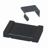
FERRITE SPLIT FILTER 20POS METAL
Manufacturer
Laird Technologies
Series
Stewardr
Type
Core-Splitr
Specifications of 28S2023-0M0
Filter Type
Flat Cable, Snap On
Shape
Rectangular
Frequency
100MHz
Impedance
250 Ohm
Package / Case
38.10mm x 6.35mm, Slot 26.67mm x 0.84mm
Shielding
Unshielded
Test Frequency
100 MHz
Product
Data Line EMI/RFI Filters
Maximum Dc Resistance
250 Ohms
Operating Temperature Range
- 40 C to + 125 C
Termination Style
Axial
Impedance, At 100 Mhz
250 Ohms
Impedance, At 25 Mhz
115 Ohms
Impedance, At 300 Mhz
520 Ohms
Material, Core
28
Special Features
Flex Cable
Termination
Cable
Lead Free Status / RoHS Status
Lead free / RoHS Compliant
Lead Free Status / RoHS Status
Lead free / RoHS Compliant, Lead free / RoHS Compliant
Other names
10705
240-2104
RC2023M
240-2104
RC2023M


Ferrite EMI Disks and Plates
Features:
• Easy installation • Each part for volume production is provided with permanent, double sided 3,5 mil acrylic adhesive
with 218 oz./inch
and error" testing • Variety of sizes offered • For frequencies above 250 MHz, H series material is generally better than
M series material • Custom parts also available.
Applications:
• Ferrite disks and plates can be utilized either as inductively-coupled components or EMI shields on PC board com-
ponents and traces. (Inductive coupling occurs when the ferrite affects the conducted wave form leaving the active
component. The rise time of the wave form is effectively slowed by the ferrite, and the overshoot and associated ringing
are attenuated. EMI shielding occurs when the ferrite absorbs the radiated emissions from active components, effectively
protecting other boards or components in the vicinity from radiated contamination). • Can be used to locate unwanted
EMI antennas. • Flat Flex & Ribbon cables. • Can also provide retrofit, auxiliary EMI attenuation.
Ferrite Disks and Plates provide a simple, cost-effective solution for radiated and inductively-coupled
electromagnetic interference. After the PC board soldering process, a ferrite disk or plate can be
installed directly on the source of EMI (such as active devices or unwanted antennas).
MM0650-100
MM0787-100
MM0787-200
MM1400-200
MM1400-300
HM0787-100
HM0787-200
HM1400-200
HM1400-300
MP0315-200
MP0350-000
MP0433-000
MP0512-200
MP0590-200
MP0591-200
MP0760-100
MP1040-100
MP1040-200
MP1040-300
MP1496-000
HP1040-100
HP1040-200
NUMBER
PART
2
adhesion. • Samples and sample kits are available with removable and reusable adhesive for "trial
(inches)
(0.787)
(0.787)
(1.400)
(1.400)
(0.650)
(0.787)
(0.787)
(1.400)
(1.400)
(1.040)
(1.040)
(0.315)
(1.040)
(0.433)
(0.512)
(0.827)
(0.591)
(0.760)
(1.040)
(1.040)
(1.040)
(1.496)
19.99
19.99
35.56
35.56
16.51
20.00
20.00
35.56
35.56
26.42
26.42
26.42
11.00
13.00
21.00
15.00
19.30
26.42
26.42
26.42
38.00
8.00
mm
A
(inches)
(1.040)
(1.040)
(0.315)
(0.350)
(0.433)
(0.512)
(0.591)
(0.591)
(0.760)
(1.040)
(1.040)
(1.040)
(1.496)
26.42
26.42
11.00
13.00
15.00
15.00
19.30
26.42
26.42
26.42
38.00
8.00
8.89
mm
B
(inches)
(0.050)
(0.075)
(0.075)
(0.100)
(0.050)
(0.050)
(0.075)
(0.075)
(0.100)
(0.050)
(0.075)
(0.079)
(0.050)
(0.077)
(0.079)
(0.079)
(0.079)
(0.050)
(0.050)
(0.075)
(0.089)
(0.079)
1.27
1.91
1.91
2.54
1.27
1.27
1.91
1.91
2.54
1.27
1.91
2.00
1.27
1.96
2.00
2.00
2.00
1.27
1.27
1.91
2.25
2.00
mm
C
Example Application Graph Explanation:
The zero line on the graph represents the base line noise recorded for an
unprotected microprocessor. The curves (dB down) represent the performance
of the Laird Technologies’ ferrite plates relative to the baseline. The addition of
the ferrite plates to the top of the processor in this specific application exhibits
up to a 5 dB EMI reduction relative to the unprotected part. In the example
application graph above, the ferrite plate MP1040-100 exhibits up to a 1 dB
advantage over the HP1040-100 from 1-100 MHz, while the HP1040-100
exhibits a 0,5 dB advantage between 200 and 400 MHz. Performance can
vary with different sizes, materials, processors and applications.
PART NUMBER SYSTEM EXAMPLE
M - Material
H - Material
-
- 1
-
-
-
-
0
1
1
MP100-100 and HP100-100
H
EXAMPLE APPLICATION
MP
HP
Disk
M - Disk
P - Plate
M
10
Frequency MHz
Indentification
Part Size
08
Plate
100
Thickness
Code
MP 1040-100
HP 1040-100
100
1000
Visit
Related parts for 28S2023-0M0
Image
Part Number
Description
Manufacturer
Datasheet
Request
R

Part Number:
Description:
Bluetooth Serial Module Development Kit
Manufacturer:
Laird Technologies
Part Number:
Description:
BLUETOOTH MODULE DEVELOPMENT KIT
Manufacturer:
Laird Technologies
Part Number:
Description:
Bluetooth 2.0 AT Data Module, Internal Antenna Development Kit
Manufacturer:
Laird Technologies

Part Number:
Description:
BLUETOOTH EVAL BOARD BTM511
Manufacturer:
Laird Technologies
Datasheet:

Part Number:
Description:
Bluetooth / 802.15.1 Modules & Development Tools BLUETTH Multimed MODLE, No ANT DEVKIT
Manufacturer:
Laird Technologies
Datasheet:

Part Number:
Description:
DEV KIT PRM122
Manufacturer:
Laird Technologies
Datasheet:
Part Number:
Description:
DEV KIT PRM123
Manufacturer:
Laird Technologies
Datasheet:

Part Number:
Description:
KIT FOR PRM112
Manufacturer:
Laird Technologies
Datasheet:
Part Number:
Description:
DEV KIT PRM121
Manufacturer:
Laird Technologies
Datasheet:

Part Number:
Description:
KIT DEVELOPMENT FOR LT2510 U.FL
Manufacturer:
Laird Technologies
Datasheet:

Part Number:
Description:
CHOKE COMMON MODE 110 OHMS SMD
Manufacturer:
Laird Technologies
Datasheet: