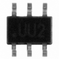
USBUF02W6 STMicroelectronics, USBUF02W6 Datasheet

USBUF02W6
Specifications of USBUF02W6
Available stocks
Related parts for USBUF02W6
USBUF02W6 Summary of contents
Page 1
... ESD protection exceeding IEC 61000-4-2 level 4 ■ High flexibility in the design of high density boards ■ Tailored to meet USB 1.1 standard February 2006 USBUFxxW6 SOTT323-6L Table 1. Order Codes Part Number USBUF01W6 USBUF02W6 Figure 1. Functional diagram Grd CODE 01 33 CODE 02 22 Tolerance ± ...
Page 2
Characteristics 1 Characteristics Table 2. Absolute ratings (T Symbol ESD discharge IEC 61000-4-2, air discharge V ESD discharge IEC 61000-4-2, contact discharge PP ESD discharge - MIL STD 883E - Method 3015-7 T Maximum junction temperature j T Storage temperature ...
Page 3
USBUFxxW6 2.1 Application example Figure 3. Implementation of ST solutions for USB ports Downstream port Gnd Gnd Downstream port Gnd Gnd 2.2 EMI filtering Current FCC regulations requires ...
Page 4
Technical information USB connectors. Distance between the USB controller and the USB connector must be minimized. The capacitors are used to bypass high frequency energy to ground and for edge t control, and are placed between ...
Page 5
USBUFxxW6 Figure 6. USBUFxxW6 ESD clamping behavior V PP ESD Surge Figure 7. Measurement board ESD SURGE 16kV Air Discharge To have a good approximation of the remaining voltages at both Vin and Vout stages, we give the typical dynamical ...
Page 6
Technical information Figure 8. Remaining voltage at both stages S1 (Vinput) and S2 (Voutput) during ESD surge Please note that the USBUFxxW6 is not only acting for positive ESD surges but also for negative ones. For these kinds of disturbances ...
Page 7
USBUFxxW6 Figure 10. Figure 10: Analog crosstalk measurements 50 Vg Figure 10. gives the measurement circuit for the analog crosstalk application. In the curve shows the effect of the D+ cell on the D-cell. In usual frequency range of analog ...
Page 8
Technical information 2.6 Transition times This low pass filter has been designed in order to meet the USB 1.1 standard requirements that implies the signal edges are maintained within the 4 -20 ns stipulated USB specification limits. To verify this ...
Page 9
USBUFxxW6 3 Packaging information Table 3. SOT323-6L Package Mechanical Data Figure 16. Recommeneded footprint (dimensions in mm) 0.80 Table 4. Mechanical specifications Lead plating Lead plating thickness Lead material Lead coplanarity Body material Flammability A ...
Page 10
... Ordering Information 4 Ordering Information Ordering code USBUF01W6 USBUF02W6 5 Revision History Date Mar-2002 Feb-2005 28-Feb-2006 10/11 Marking Package Weight UU1 SOT323-6L 5.4 mg UU2 SOT323-6L 5.4 mg Revision 3A Last update. 4 Layout update. No content change. Operating temperature range updated to -40 to 70° Layout updated to current standard. ...
Page 11
... USBUFxxW6 Information in this document is provided solely in connection with ST products. STMicroelectronics NV and its subsidiaries (“ST”) reserve the right to make changes, corrections, modifications or improvements, to this document, and the products and services described herein at any time, without notice. All ST products are sold pursuant to ST’s terms and conditions of sale. ...


