PAXLC600 Red Lion Controls, PAXLC600 Datasheet - Page 7
PAXLC600
Manufacturer Part Number
PAXLC600
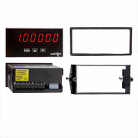
Description
COUNTER 6-DIGIT BI-DIR COUNT
Manufacturer
Red Lion Controls
Series
PAX®LITEr
Type
Counterr
Specifications of PAXLC600
Count Rate
25kHz
Number Of Digits/alpha
6
Input Type
Voltage
Voltage - Supply
10 V ~ 16 VDC,115 VAC, 230 VAC
Display Type
LED Red
No. Of Digits / Alpha
6
Digit Height
14.2mm
Power Consumption
6VA
Operating Temperature Range
0°C To +60°C
Signal Input Type
Pulse
Character Size
0.56"
Ip/nema Rating
IP65 / NEMA 4X
Connection Type
Cage-Clamp
Cut Out, Panel
3.62×1.77 "
Dimensions
4.2"L×3.8"W×1.95"H
Display Digit Height
0.56 "
Function
Counter
Number Of Digits
6
Primary Type
Electronic
Range, Measurement
-99999 to 999999
Special Features
Programmable
Termination
Terminal Block
Voltage, Supply
115/230 VAC, 10 to 16 VDC
Counter Supply Voltage
115/230VAC/10-16VDC
Display Font Color
Red
Rohs Compliant
Yes
Lead Free Status / RoHS Status
Lead free / RoHS Compliant
Output Type
-
Lead Free Status / Rohs Status
RoHS Compliant part
Other names
RLC101


sequence shown above, using the front panel push buttons.
the Decimal Position, Scale Factor and Scale Multiplier to use for the specific
application.
switch. With the switch in the Disabled (up) position the meter will not enter
programming mode. Refer to the section on DIP switch setup.
PROGRAMMING MODE ENTRY
PROGRAMMING PARAMETERS
current selection or value for that parameter. The dual display with arrows is
used below to illustrate the alternating display. The selection choices or value
range for each parameter is shown to the right of the alternating display.
display.
desired selection is shown. Press the PAR key to save the displayed selection
and advance to the next parameter.
Factor and the Scale Multiplier to obtain the desired process value. A Scale
Factor of 1.00000 and a Scale Multiplier of 1 will result in the display of the
actual number of input counts. (See details on scaling calculations.)
flashing (initially digit 6). Press the (up arrow) key to increment the value of
the selected (flashing) digit. Holding the key automatically scrolls the value
of the selected digit.
Use the key to increment the value of this digit to the desired number. Press
the key again to select the next digit to be changed. Holding the key
automatically scrolls through each digit position. Repeat the “select and set”
sequence until all digits are displaying the desired Scale Factor value. Press the
PAR key to save the displayed value and advance to the next parameter.
6.0 P
The Totalizer has four programmable parameters which are entered in the
Note: Programming mode can be locked out with the Program Disable DIP
Press the PAR key to enter Programming Mode. The meter briefly displays
In programming mode, the display alternates between the parameter and the
Press the arrow keys ( or ) to sequence through the selection list until the
The Scale Factor is displayed as a six-digit value with one selected digit
Press the (down arrow) key to select the next digit position to the right.
Before programming, refer to the section on Scaling the Meter to determine
followed by the first programming parameter described below.
PAR
COUNTER
DISPLAY
Pro
ROGRAMMING THE
This parameter selects the decimal point position on the
The number of input counts is multiplied by the Scale
DECIMAL POSITION
SCALE FACTOR
dEC Pt
Decimal
Position
to
PAR
PROGRAMMING SEQUENCE
SC FAC
Factor
Scale
PAR
M
7
ETER
Scale Factor to obtain the desired process value. A Scale Multiplier of 1 will
result in only the Scale Factor affecting the display. (See details on scaling
calculations.)
desired selection is displayed. Press the PAR key to save the selection and exit
programming mode.
PROGRAMMING MODE EXIT
Scale Multiplier selection. The meter briefly displays
Programming Mode. All programmed selections are now transferred to the non-
volatile memory and the meter returns to the Counter display.
and reprogram, if necessary, when power is restored.)
PROGRAMMING MODE TIME OUT
activity is detected for approximately 60 seconds, the meter automatically exits
Programming Mode. The meter briefly displays
display. When automatic timeout occurs, any changes that were made to the
parameter currently being programmed, will not be saved.
FACTORY SETTINGS
alternating display illustrations. The factory settings can be easily restored by
removing power from the meter, and then pressing and holding the PAR key
while power is reapplied. The meter displays
released. The normal power-up sequence then resumes, with the factory settings
loaded and saved in non-volatile memory. The Count is reset to 0.
position to allow loading factory settings. See section on DIP switch setup.
SCALEr
Multiplier
The number of input counts is multiplied by the Scale Multiplier and the
Press the arrow keys ( or ) to sequence through the selection list until the
The totalizer may be programmed to reset at each meter power-up.
The meter exits Programming Mode when the PAR key is pressed to save the
(If power loss occurs during programming mode, verify parameter changes
The Programming Mode has an automatic time out feature. If no keypad
The factory settings for the programming parameters are shown above in the
Note: The Program Disable DIP switch must be in the Enabled (down)
Scale
PAR
COUNTER RESET AT POWER-UP
SCALE MULTIPLIER
r P-UP
Power-Up
PAR
COUNTER
DISPLAY
End
and returns to the Counter
until the PAR key is
upon exiting