SCUBD-200/A Red Lion Controls, SCUBD-200/A Datasheet - Page 3
SCUBD-200/A
Manufacturer Part Number
SCUBD-200/A
Description
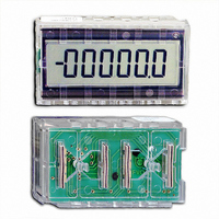
COUNTER LCD COMPONENT 6 DIGIT
Manufacturer
Red Lion Controls
Series
SUB-CUBr
Datasheet
1.SCUBD-200A.pdf
(8 pages)
Specifications of SCUBD-200/A
Count Rate
500kHz
Number Of Digits/alpha
8
Input Type
Voltage
Voltage - Supply
2.5 V ~ 6.0 V
Display Type
LCD Non-Backlit
Lead Free Status / RoHS Status
Lead free / RoHS Compliant
Output Type
-
Other names
RLC05
SCUBD
SCUBD-200
SCUBD
SCUBD-200


BI-DIRECTIONAL COUNTING MODES
“B” serves as the direction control input. In the Times 1 Mode when “B” is at a
low level, a negative going transition at “A” will cause the counter to count in
the positive direction. When “B” is at a high level, a negative going transition at
“A” will cause the counter to count in the negative direction. Table 1 illustrates
the level settings of the Mode Select Inputs for the various modes of Bi-
Directional counting. The Times 2 Mode works like Times 1 Mode except the
counter increments on both the positive and negative going transitions at “A”.
There are also two Divide-By Modes which prescale the display by 10 or by 100.
This results in the capability of displaying the 7th and 8th digit of the internal
counter. (Along with Times 2, this gives an equivalent ÷ 5 and ÷ 50 display.)
QUADRATURE COUNTING MODES
input “B” serves as the quadrature input. (Input “B” is a pulse train shifted 90°
away from “A”.) The counter will count in a positive going direction when “A”
is a negative going signal and “B” is low. The counter will count in a negative
going direction when “A” is a positive going signal and “B” is low. All
transitions on “A” are ignored when “B” is high. These logic rules provide the
basis for anti-jitter operation which will prevent false counts from occurring,
due to back-lash, vibration, chatter, etc.
modes of Quadrature counting. The Times 2 Quadrature Mode works the same
as Times 1 when “B” is low. But when “B” is high, counts are no longer
ignored at “A”. Instead, the logic rules for “A” are complemented, allowing
both edges of “A” to be counted. This gives an effective doubling of display
count but more importantly, doubles the resolution of the input. The Times 4
Mode extends this even further. Both “A” and “B” serve as count or quadrature
input. In one instance, “A” will be the count input and “B” will be the
quadrature input. In another instance, “B” will be the count input and “A” will
be the quadrature input. This will result in counts and resolution four (4) times
greater than in the Times 1 Mode. For counting rates on these modes, refer to
the specification sheet (X2, X4, ÷10, ÷100 give an equivalent divide-by 2.5, 5,
25, and 50).
For Bi-Directional counting, input “A” serves as the count input, while input
For Quadrature Times 1 counting, input “A” serves as the count input while
Table 2 illustrates the level settings of the Mode Select Inputs for the various
Times 1
Times 2
(x2, ÷10)
Divide by 5*
(x1, ÷10)
Divide by 10
(x2, ÷100)
Divide by 50*
(x1, ÷100)
Divide by 100
*
Times 1
Times 2
Times 4
(x4, ÷10)
Divide by 2.5*
(x2, ÷10)
Divide by 5*
(x1, ÷10)
Divide by 10
(x4, ÷100)
Divide by 25*
(x2, ÷100)
Divide by 50*
(x1, ÷100)
Divide by 100
*
These factors include both a resolution multiplier and a decade
These factors include both a resolution multiplier and a decade
prescaler.
prescaler.
MODE
1 = V
MODE
1 = V
DD
DD
= High Level
= High Level
TABLE 1
TABLE 2
MS4
MS4
0
0
0
0
0
0
0
1
1
1
1
1
1
1
1
0 = V
0 = V
MS3
MS3
0
1
0
1
0
1
1
0
0
1
0
1
1
0
1
SS
SS
= Low Level
= Low Level
MS2
MS2
0
1
1
0
1
0
1
0
0
0
1
1
0
1
1
MODES OF OPERATION
MS1
MS1
0
0
0
1
1
0
1
0
1
1
0
0
0
1
1
3
DECIMAL POINT AND LEADING ZERO BLANKING
SELECTION
DP3), and two signal outputs from the counter chip. A decimal point is turned
OFF when the LCD input is connected to the BP signal output; or turned ON
when it is connected to the BP output. Refer to Table 3.
determined by the settings of the LZB inputs. Table 4 illustrates the level
settings required for a display of a single 0, to one with no leading zero
blanking. Note that the decimal point position is set independently of the
selection of leading zeros.
The SUB CUB D has three decimal point inputs to the LCD (DP1, DP2, and
The number of leading zeros present on the SUB CUB D display is
* Test Mode is intended for factory use only.
Test Mode*
No DP
1st DP
2nd DP
3rd DP
MODES
000000
00000
0000
000
00
0
D.P.3
TABLE 4
LZB3
BP
BP
BP
BP
TABLE 3
0
0
0
0
1
1
1
LZB2
D.P.2
BP
BP
BP
BP
0
0
1
1
0
0
1
LZB1
D.P.1
BP
BP
BP
BP
0
1
0
1
0
1
0