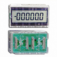
SCUBD-200/A Red Lion Controls, SCUBD-200/A Datasheet - Page 4

SCUBD-200/A
Manufacturer Part Number
SCUBD-200/A
Description
COUNTER LCD COMPONENT 6 DIGIT
Manufacturer
Red Lion Controls
Series
SUB-CUBr
Datasheet
1.SCUBD-200A.pdf
(8 pages)
Specifications of SCUBD-200/A
Count Rate
500kHz
Number Of Digits/alpha
8
Input Type
Voltage
Voltage - Supply
2.5 V ~ 6.0 V
Display Type
LCD Non-Backlit
Lead Free Status / RoHS Status
Lead free / RoHS Compliant
Output Type
-
Other names
RLC05
SCUBD
SCUBD-200
SCUBD
SCUBD-200
TYPICAL APPLICATIONS
QUADRATURE TIMES FOUR
of a work table. The work table can be moved left or right and is driven
by a lead screw. Because the two requirements of critical positioning
and direction reversal must be satisfied, the Quadrature Mode of the
SUB CUB D is selected. An RPGB with 10 PPR, quadrature, current
sinking output is coupled to the screw shaft. The screw shaft moves the
table one inch for every 25 revolutions which yields 250 pulses/inch of
travel. But in this application, a higher degree of resolution is needed
without using a higher resolution sensor. Therefore, the Times Four
Quadrature Mode is selected which results in a reading of 1000 counts
per inch of travel or 0.001" increments of resolution.
lines, including buffering of the two inputs. (The diodes are used to
block the 12 VDC signal of the RPGB from the SUB CUB D inputs.)
The decimal point is placed in the third position so the reading is in
one-thousandth of an inch.
reference point desired, reset the SUB CUB D and make all
measurements with regard to this reference. Movement to the left of
this reference will provide a negative reading, while movement to the
right of the reference will provide a positive numerical reading.
Switching the count and quadrature inputs will cause movement left to
be positive (+) while movement to the right will be negative (-). As
shown in the drawing, the work table is 53.475" to the left of the
reference point.
In this application, it is necessary to keep track of the exact position
The drawing illustrates connections for the inputs and mode select
With the set-up shown, the operator can place the table at any
4
BI-DIRECTION UP/DOWN COUNTING
to a flexible material, which is then taken up on a large roll.
Whenever a flaw is detected, the entire process is stopped. Since
inertia exists in the system, a certain amount of over-run will
occur. This, in turn, will require reversing the system in order to
bring the flaw back to the adhesive applicator. The SUB CUB D
can be used to correct over-run problem by causing the count to
decrease when the process is reversed.
counting. The Latch pin is used to “freeze” the display when a
defect occurs. Input “A” serves as the count input which is
connected to an open collector output LSC Length Sensor. This
sensor generates 100 pulses/foot of material travel. (With 100
pulses/foot going into the counter, the decimal point is selected so
that the display will indicate hundreths of feet.) Input “B” serves
as the UP/DOWN direction control pin. This pin is connected to
a contact which opens when the system reverses direction,
causing the counter to count “down”. Since the unit is measuring
in hundreths of a foot and very large rolls are used, it is possible
that the count could exceed the display capability of six (6)
digits. To avoid this problem, a button is connected which, when
pressed, causes the unit to display the six (6) most significant
digits of the internal 8-digit counter. In addition, the decimal
point is removed when the button is held down.
Whenever a flaw is detected, the Latch pin will be pulled high,
“freezing” the display at the reading where the flaw occurred. At
the same time, the machine is stopped and the applicator is turned
off. Due to inertia within the system, internal counts increase
until the system comes to a complete stop. The operator then
notes the reading on the counter display, releases the latch pin
(the display then reveals the total length), and reverses the
machine until the displayed value matches the noted value.
When this match occurs, the flawed area is beneath the applicator
area where it can be corrected.
In this application, a continuous coating of adhesive is applied
The SUB CUB D is set for Bi-Directional UP/ DOWN
The operation of the system is described as follows.


