ACA-20RM-1-AC3-RL-C Murata Power Solutions Inc, ACA-20RM-1-AC3-RL-C Datasheet - Page 3
ACA-20RM-1-AC3-RL-C
Manufacturer Part Number
ACA-20RM-1-AC3-RL-C
Description
METER LED 120VAC 2A TRU-RMS RED
Manufacturer
Murata Power Solutions Inc
Type
Ammeterr
Series
ACA-20RMr
Datasheet
1.ACA-20RM-5-AC3-RL-C.pdf
(5 pages)
Specifications of ACA-20RM-1-AC3-RL-C
Display Type
LED
Measuring Range
0 ~ 1.999A
Display Style
Red Characters, Black Background
Display Digits
3.5
Display Digits - Height
0.370" (9.40mm)
Backlight
Without
Mounting Type
Panel Mount
Termination
Terminal Block
Voltage - Supply
85 ~ 140VAC
Equipment Type
AC Ammeters
Primary Voltage Rating
85 V to 140 V
Secondary Current Rating
30 mA
Lead Free Status / RoHS Status
Lead free / RoHS Compliant
Display Face Size
-
Lead Free Status / Rohs Status
Lead free / RoHS Compliant
Other names
811-1111


3. Wire Gauges and Fusing: Wires specifi ed in the Functional Specifi -
4. AC Supply Polarity and Grounding: The two supply inputs, TB1 ‘A’ and
WIRING DIAGRAMS
First pass and carefully dress one external load wire through L1, then
connect the AC supply and load wires to TB1 as shown. Ensure all wires
are stripped and properly tightened. For accurate operation, make only
The calibration potentiometer has approximately ¾ of a turn of rotation;
do not force its adjustment screw past the end stops. Contact MPS if
additional information is required regarding calibration, setup, or any
other technical issue pertaining to ACA-20RM ac ammeters.
cations section must be used for making connections to ACA-20RM
series ammeters. All power-supply and load wiring must be rated for
the supply voltages and currents they will conduct and must comply
with any code or application-mandated requirements pertaining to the
user’s specifi c installation.
ACA-20RM ammeters are not internally fused. Terminal block TB1 is to
be used only for powering the ammeter’s internal circuitry; it must not
be used to supply power to external loads. The supply wires feeding
these ammeters must be fused with a 0.25A/250V time delay/time lag
fuse, in accordance with applicable regulatory codes.
Wire insulation must be stripped to within ±10% of the stated dimen-
sions, and wires should be inserted into TB1 such that their insulation
is not pinched by the screw terminal.
‘B’, on ACA-20RM ammeters are not polarity sensitive, that is, they have
no ‘AC LO’ or ‘AC HI’ designations. Also, ac-powered ACA-20RM amme-
ters do not include or require a connection to earth/chassis ground.
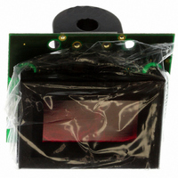
Figure 2. Connections for pc-board mounted CT's
BACK VIEW
www.murata-ps.com/dpm
5. Connector Torque Ratings: Be sure to tighten TB1’s screw-terminals
6. Isolation: The on-board CT (L1) provides a minimum of 2000Vdc iso-
7. Split-Core CT (Clamp-on) Models: 50A models feature a split-core
one pass with load wire through the on-board CT (only one primary turn).
For split-core CT models, make sure to fully engage the CT's Locking
mechanism
to 3.6 pound-inches (0.4Nm). Proper tightening will ensure reliable
long-term operation.
lation between the current-carrying load conductor passing through
its opening and the ammeter’s power source that’s connected to TB1.
Of course, this isolation rating applies only to applications where the
load wire does not connect directly or indirectly to TB1-A or TB1-B
(i.e., where two different ac supplies are involved).
current transformer that can be clamped around a current-carrying
load conductor without having to disconnect or remove power from
the load’s power source. This live-connection capability can only
be used if the load’s power source is isolated (see technical note 6)
from the ammeter’s own power source that’s connected to TB1.
The ammeter’s ac power supply must always be denergized before
making connections to TB1. Refer to the ‘Panel Installation’ section of
this data sheet for additional information.
True-RMS-AC Ammeters with Built-in CT
Figure 3. Connection for fl ying lead CT's
26 Jan 2011 MPM_ACA-20RM_B05 Page 3 of 5
ACA-20RM Series
BACK VIEW
email: sales@murata-ps.com