ACA-20RM-4-AC4-RL-ALM-C Murata Power Solutions Inc, ACA-20RM-4-AC4-RL-ALM-C Datasheet - Page 2
ACA-20RM-4-AC4-RL-ALM-C
Manufacturer Part Number
ACA-20RM-4-AC4-RL-ALM-C
Description
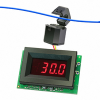
AMMETER AC 50A 220V W/ALARM RED
Manufacturer
Murata Power Solutions Inc
Series
ACA-20RM-ALMr
Type
Ammeterr
Datasheet
1.ACA-20RM-5-AC3-RL-ALM-C.pdf
(5 pages)
Specifications of ACA-20RM-4-AC4-RL-ALM-C
Display Type
LED
Measuring Range
0 ~ 50.0A
Display Style
Red Characters, Black Background
Display Digits
3.5
Display Digits - Height
0.370" (9.40mm)
Backlight
Without
Mounting Type
Panel Mount
Termination
Terminal Block
Voltage - Supply
170 ~ 264VAC
Dimensions
53.34 mm L x 35.56 mm W x 18.54 mm H
Mounting Style
Panel
Primary Voltage Rating
170 V to 264 V
Secondary Current Rating
50 A
Lead Free Status / RoHS Status
Lead free / RoHS Compliant
Display Face Size
-
Lead Free Status / Rohs Status
Lead free / RoHS Compliant
Other names
811-1981


Performance/Functional Specifi cations
Typical at T
Rated Full-Scale Current ➀
ACA-20RM-4-ACX-RL-ALM
ACA-20RM-5-ACX-RL-ALM
Overcurrent Rating ➁
Performance
Sampling Rate
Accuracy ➂
Measurement Type
Temperature Drift (0 to 60 °C)
Zero-Current Reading (within
30 sec.)
Dielectric Withstanding Voltage
Power Supply Voltage
ACA-20RM-X-AC3-RL-ALM
ACA-20RM-X-AC4-RL-ALM
Power Supply Current ➃
ACA-20RM-X-AC3-RL-ALM
ACA-20RM-X-AC4-RL-ALM
Alarm Function
Display indication
Settable range
Power Supply Terminal Block
Wire Size
Insulation Strip Length
Screw Tightening Torque
Rated Voltage
Display
Display Type and Size
Overrange Indication
Decimal Point
Physical/Environmental
Operating Temperature
Storage Temperature
Humidity (non-condensing)
Dimensions
Weight
ACA-20RM-4-XXX-XX-ALM
ACA-20RM-5-XXX-XX-ALM
ACA-20RM-4-ACX-RL-ALM
ACA-20RM-5-ACX-RL-ALM
A
= +25°C, unless otherwise noted.
–001
Flashing Display with actual current
reading and display intensity change
1.5 Ounces (43 grams) nominal
2.1 Ounces (60 grams) nominal
2000
Min.
170
–40
rms Responding, Crest Factors of 1-5
3½ Digit Red LED, 0.37”/9.4mm High
—
—
—
85
—
—
13
8
0
0
Model dependent, see page 4 & 5
±0.4%FS ±3 Counts with 60Hz
1.5 x Rated Full-Scale Current
16-22AWG, Solid or stranded
(see full-scale input current)
3.6 pounds-inches (0.4Nm)
2.5 Samples per second
Fixed, model dependent
±0.2
Typ.
000
120
220
—
—
—
30
30
45
24
—
—
—
Sine-Wave Input
0.250 inches
“1___”
310Vac
Max.
±0.4
50.0
30.0
001
140
264
+60
+75
—
50
50
50
30
85
Vac/47-63Hz
Vac/47-63Hz
mA/47-63Hz
mA/47-63Hz
Counts/ºC
Amperes
Amperes
www.murata-ps.com/dpm
Counts
Units
Amps
Amps
Vdc
°C
°C
%
➀ Specifi ed full-scale currents are those passing through the ammeter’s built-in
➁ The overcurrent rating of 1.5 x the rated full-scale current is a continuous rating
➂ Specifi ed accuracy applies to inputs with crest factors (CF) up to 2.0, where CF
➃ All specifi ed maximum power supply currents are steady state; larger surge
TECHNICAL NOTES
ACA-20RM-4-AC3-RL-ALM-C
ACA-20RM-4-AC4-RL-ALM-C
ACA-20RM-5-AC3-RL-ALM-C
ACA-20RM-5-AC4-RL-ALM-C
1. Measurement Type: ACA-20RM-ALM ac ammeters employ a
2. Calibration (Potentiometer R7): Periodic recalibration of ACA-
3. Overcurrent Alarm Setup and Adjustment (Potentiometer R3):
Ordering Information
current transformer’s primary load-circuit. See Notes 2 and 3 below for ad-
ditional model-specifi c information.
and applies to the current passing through the built in current transformer only,
it does not apply to any external circuit-wiring or external loads. Accuracy is
guaranteed up to the rated current level.
= Vpeak/Vrms. Crest factors of 2 to 5 introduce an additional error of ±3% of full
scale. Ammeters are calibrated with a near full-scale 60Hz sine-wave current
fl owing through the ammeter’s built-in CT.
currents can occur at initial application of line power.
IMPORTANT! To ensure safe and reliable operation, ACA-20RM-
ALM ammeters must be installed and serviced by qualifi ed
technical personnel. Contact Murata Power Solutions if there is
any doubt regarding ammeter setup, installation, or operation.
true-rms input circuit to measure current fl owing through L1. Stated
accuracy specifi cations are measured using a sine-wave current
at, or close to, the ammeter’s full-scale input range, at nominal line
frequency of 60Hz.
20RM-ALM ammeters is not required under normal, indoor operating
environments. If user calibration is necessary, it must be performed
by qualifi ed technical personnel. Calibration is performed with poten-
tially lethal voltages applied to the ACA-20RM-ALM and its associated
wiring. A plastic, fully-insulated adjusting tool must be used to access
the calibration potentiometer R7 located on the back of the ammeter
(see ‘Mechanical Specifi cations’ section). Contact MPS if additional
information is required regarding calibration, setup, or any other
technical issue pertaining to ACA-20RM-ALM ammeters.
ACA-20RM-ALM ammeters feature a user-settable, overcurrent visual
alarm indication which can be used to alert operators that a load cir-
cuit breaker or fuse is approaching an overload condition. When the
load current sensed by L1 exceeds this preset level, the ammeter’s
LED display will fl ash from normal intensity to dim intensity at rate of
approximately 1.5 times per second.
As shown in Figure 3, the alarm circuit consists of jumper JP1, and
adjustment potentiometer R3. As shipped, R3 is factory set to trip
when the load current is approximately 24 Amps for 30A models, and
approximately 45 Amps for 50A models. When R3 is set to its maxi-
mum clockwise position, the alarm indication will not activate until the
load current fl owing through L1 exceeds the maximum rating of the
ammeter, i.e., above 30.0A, or above 50.0A, depending on the model.
True-rms-AC Ammeters with Alarm Function
ACA-20RM-ALM Series
15 Mar 2011 MPM_ACA-20RM-ALM.A04 Page 2 of 5
50.0A Range (split-core CT), 85-140Vac power
50.0A Range (split core CT), 170-264Vac power
30.0A Range, 85-140Vac power
30.0A Range, 170-264Vac power
email: sales@murata-ps.com