ACA-20RM-4-AC4-RL-ALM-C Murata Power Solutions Inc, ACA-20RM-4-AC4-RL-ALM-C Datasheet - Page 4
ACA-20RM-4-AC4-RL-ALM-C
Manufacturer Part Number
ACA-20RM-4-AC4-RL-ALM-C
Description
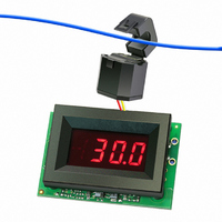
AMMETER AC 50A 220V W/ALARM RED
Manufacturer
Murata Power Solutions Inc
Series
ACA-20RM-ALMr
Type
Ammeterr
Datasheet
1.ACA-20RM-5-AC3-RL-ALM-C.pdf
(5 pages)
Specifications of ACA-20RM-4-AC4-RL-ALM-C
Display Type
LED
Measuring Range
0 ~ 50.0A
Display Style
Red Characters, Black Background
Display Digits
3.5
Display Digits - Height
0.370" (9.40mm)
Backlight
Without
Mounting Type
Panel Mount
Termination
Terminal Block
Voltage - Supply
170 ~ 264VAC
Dimensions
53.34 mm L x 35.56 mm W x 18.54 mm H
Mounting Style
Panel
Primary Voltage Rating
170 V to 264 V
Secondary Current Rating
50 A
Lead Free Status / RoHS Status
Lead free / RoHS Compliant
Display Face Size
-
Lead Free Status / Rohs Status
Lead free / RoHS Compliant
Other names
811-1981


BEZEL AND PANEL CUTOUT
PANEL INSTALLATION
All connections to ACA-20RM-ALM Series ammeters must be made after
the ammeter is securely attached to the panel and with all associated
load and supply voltages de-energized (off), using extreme caution and
observing all safety measures applicable to the user’s installation.
Care should be exercised when passing conductors through the amme-
ter’s built-in current transformer L1. The installed wire-positions should
be such that minimal mechanical forces are applied to L1, TB1, or to the
ammeter itself. In high-vibration environments, it is strongly recom-
mended that adequate strain reliefs be used for all wiring.
Using Figure 4 as a guide, carefully insert the bezel/color fi lter assembly
into the panel opening. From the rear of the panel, install the four round
Bezel
Gasket
FRONT V IEW
1.826 ( 46.38)
PANEL
SIDE VIEW
(4.75)
0.187
(32.51)
Standoff
1.280
www.murata-ps.com/dpm
Nut
Figure 4. Panel Installation
AC Ammeter
ACA-20RM
(17.5)
0.69
(27.18)
0.093 ( 2.362) D IAMETER ( 4 R EQUIRED)
plastic standoffs over the bezel’s threaded studs. Install the ACA-20RM-
ALM pc-board assembly as shown and then attach and securely tighten
all four hex nuts. Use only the factory-supplied hardware as the use
of substitute hardware could result in an unsafe installation and/or
adversely affect the reliability of the ammeter.
The recommended range of panel thickness that can be used with the
supplied hardware is 0.040 inches (1.0mm) to 0.125 inches (3.2mm).
Panel thickness outside of this range will require additional user-supplied
hardware or modifi cations.
0.032 (0.8) Thick
1.07
Gasket
True-rms-AC Ammeters with Alarm Function
INTERNAL C ORNER R ADII:
ACA-20RM-ALM Series
PANEL C UTOUT D IMENSIONS
RECOMMENDED D RILL A ND
0.032 ( 0.81) M AX.
1.336 ( 33.93)
1.626 ( 41.30)
15 Mar 2011 MPM_ACA-20RM-ALM.A04 Page 4 of 5
Standoff
0.190 (4.83)
email: sales@murata-ps.com
0.145 ( 3.68)
0.116 ( 2.95)
(21.29)
0.838