PAXLID00 Red Lion Controls, PAXLID00 Datasheet - Page 5
PAXLID00
Manufacturer Part Number
PAXLID00
Description
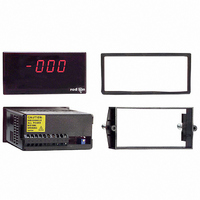
METER DC CURRENT 3 1/2-DIGIT
Manufacturer
Red Lion Controls
Series
PAX®LITEr
Type
Ammeterr
Datasheet
1.PAXLID00.pdf
(8 pages)
Specifications of PAXLID00
Measuring Range
0 ~ 199.9mA
Display Style
Red Characters, Black Background
Display Type
LED
Display Face Size
3.80" L x 1.95" W (96.5 x 49.5mm)
Display Digits
3.5
Display Digits - Height
0.560" (14.22mm)
Backlight
Without
Mounting Type
Panel Mount
Termination
Terminal Block
Voltage - Supply
115VAC,230 VAC
No. Of Digits / Alpha
3-1/2
Meter Function
DC Ammeter
Meter Range
199.9uA To 1.999A
Digit Height
14.2mm
Power Consumption
6VA
Operating Temperature Range
0°C To +60°C
Supply Voltage Ac, Min
115V
Accuracy
±0.1% (199.9 µA to 19.99 mA)
Connection Type
Cage-Clamp
Cut Out, Panel
3.62×1.77 "
Dimensions
4.2"L×3.8"W×1.95"H
Display Digit Height
0.56 "
Display Resolution
0.1 μA to 1 mA
Function
Ammeter
Meter Type
DC Current
Number Of Digits
3-1/2
Primary Type
Electronic
Range, Measurement
199.9 μADC to 1.999 ADC
Special Features
Multi-Range Unit
Standards
cULus Listed, CE Marked
Temperature, Operating
0 to 60 °C
Time, Response
1 Second nominal
Voltage, Supply
115/230 VAC
Weight
0.65 lbs
Character Size
0.56"
Display Font Color
Red
Rohs Compliant
NA
Lead Free Status / RoHS Status
Lead free / RoHS Compliant
Lead Free Status / RoHS Status
na, Lead free / RoHS Compliant
Other names
RLC105


WIRING OVERVIEW
back of the meter. All conductors should conform to the meter’s voltage and
current ratings. All cabling should conform to appropriate standards of good
installation, local codes and regulations. It is recommended that power supplied
to the meter (AC) be protected by a fuse or circuit breaker.
meter case against those shown in wiring drawings for proper wire position. Strip
the wire, leaving approximately 0.3" (7.5 mm) bare lead exposed (stranded wires
should be tinned with solder). Insert the lead under the correct screw-clamp
terminal and tighten until the wire is secure. (Pull wire to verify tightness.)
EMC INSTALLATION GUIDELINES
Magnetic Interference (EMI), proper installation and wiring methods must be
followed to ensure compatibility in each application. The type of the electrical
noise, its source or the method of coupling into the unit may be different for
various installations. Listed below are some EMC guidelines for successful
installation in an industrial environment.
1. The meter should be mounted in a metal enclosure, which is properly
2. Never run Signal or Control cables in the same conduit or raceway with AC
3. Signal or Control cables within an enclosure should be routed as far away as
PAXLV Jumper Selection
3.0 W
Electrical connections are made via screw-clamp terminals located on the
When wiring the meter, compare the numbers embossed on the back of the
Although this meter is designed with a high degree of immunity to Electro-
connected to protective earth.
power lines, conductors feeding motors, solenoids, SCR controls, and
heaters, etc. The cables should be run in metal conduit that is properly
grounded. This is especially useful in applications where cable runs are long
and portable two-way radios are used in close proximity or if the installation
is near a commercial radio transmitter.
possible from contactors, control relays, transformers, and other noisy
components.
Main
Circuit
Board
REAR TERMINALS
FRONT DISPLAY
IRING THE
SELECTION
POWER
SWITCH
INPUT RANGE
JUMPER
SWITCHES
SET-UP
SCALING
DIP
POT
M
ON
ETER
5
4
3
2
1
5
4. In extremely high EMI environments, the use of external EMI suppression
5. Long cable runs are more susceptible to EMI pickup than short cable runs.
6. Switching of inductive loads produces high EMI. Use of snubbers across
devices, such as ferrite suppression cores, is effective. Install them on Signal
and Control cables as close to the unit as possible. Loop the cable through the
core several times or use multiple cores on each cable for additional protection.
Install line filters on the power input cable to the unit to suppress power line
interference. Install them near the power entry point of the enclosure. The
following EMI suppression devices (or equivalent) are recommended:
Therefore, keep cable runs as short as possible.
inductive loads suppresses EMI.
Ferrite Suppression Cores for signal and control cables:
Line Filters for input power cables:
Note: Reference manufacturer’s instructions when installing a line filter.
Snubber: RLC#SNUB0000.
Fair-Rite # 0443167251 (RLC #FCOR0000)
TDK # ZCAT3035-1330A
Steward #28B2029-0A0
Schaffner # FN610-1/07 (RLC #LFIL0000)
Schaffner # FN670-1.8/07
Corcom #1VR3
THIS AREA!
JUMPER IN
ONLY ONE
JUMPER SELECTIONS
The
INPUT RANGE JUMPER
REAR TERMINALS
indicates factory setting.
VOLT
±19.99V
±300V
±1.999V
±199.9V