PAXLTC00 Red Lion Controls, PAXLTC00 Datasheet - Page 5
PAXLTC00
Manufacturer Part Number
PAXLTC00
Description
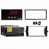
METER THERMOCOUPLE 4-DIGIT
Manufacturer
Red Lion Controls
Series
PAX®LITEr
Type
Thermocoupler
Datasheet
1.PAXLTC00.pdf
(8 pages)
Specifications of PAXLTC00
Display Style
Red Characters, Black Background
Display Type
LED Red
Display Face Size
3.80" L x 1.95" W (96.5 x 49.5mm)
Display Digits
4
Display Digits - Height
0.560" (14.22mm)
Mounting Type
Panel Mount
Termination
Terminal Block
Voltage - Supply
85 V ~ 250 VAC
Applications
Thermocouple Input - Type T, E, J, K, R, S, B, N, or mV
Number Of Digits/alpha
4
No. Of Digits / Alpha
4
Meter Function
Temperature
Digit Height
14.2mm
Power Consumption
6VA
Operating Temperature Range
0°C To +50°C
Supply Voltage Ac, Min
85V
Signal Input Type
Selectable Thermocouple
Accuracy
0.8 °C, 2.1 °C, 2.3 °C °C
Brand/series
PAXL Series
Connection Type
Cage-Clamp
Cut Out, Panel
3.62×1.77 "
Dimensions
4.2"L×3.8"W×1.95"H
Display Digit Height
0.56 "
Display Resolution
1 °
Frequency
50⁄60 Hz
Function
Temperature
Number Of Digits
4
Primary Type
Electronic
Range, Measurement
-200 to +400 °C for T, -200 to +1000 °C for E, -200 to +760 °C for J, -200 to +1250 °C for K, 0 to +1768 °C for R, +150 to +1820 °C for B, -200 to +1300
Resolution
1 °
Standards
UL Recognized, CSA Certified, CE Approved
Temperature, Operating
0 to 50 °C
Temperature, Range, Measuring
-200 to +400 °C
Thermocouple Type
T
Voltage, Operating
85 to 250 VAC
Voltage, Supply
85 to 250 VAC
Character Size
0.56"
Display Font Color
Red
Rohs Compliant
NA
Lead Free Status / RoHS Status
Contains lead / RoHS non-compliant
Lead Free Status / RoHS Status
na, Contains lead / RoHS non-compliant
Other names
RLC116


EMC INSTALLATION GUIDELINES
Magnetic Interference (EMI), proper installation and wiring methods must be
followed to ensure compatibility in each application. The type of the electrical
noise, source or coupling method into the meter may be different for various
installations. The meter becomes more immune to EMI with fewer I/O
connections. Cable length, routing, and shield termination are very important
and can mean the difference between a successful or troublesome installation.
Listed below are some EMC guidelines for successful installation in an
industrial environment.
1. The meter should be mounted in a metal enclosure, which is properly
2. Use shielded (screened) cables for all Signal and Control inputs. The shield
3. Never run Signal or Control cables in the same conduit or raceway with AC
PEAK/VALLEY DETECTION
lowest input reading (valley) for later recall. These values are stored at power-
down to allow monitoring the process limits over any length of time (shifts, days,
etc.). A selectable capture delay time is used to prevent detection of false peak or
valley readings caused by sudden short spikes or unusual process events.
keys as described below.
3.0 R
Although this meter is designed with a high degree of immunity to Electro-
connected to protective earth.
(screen) pigtail connection should be made as short as possible. The
connection point for the shield depends somewhat upon the application.
Listed below are the recommended methods of connecting the shield, in order
of their effectiveness.
a. Connect the shield only at the panel where the unit is mounted to earth
b. Connect the shield to earth ground at both ends of the cable, usually when
c. Connect the shield to common of the meter and leave the other end of the
power lines, conductors feeding motors, solenoids, SCR controls, and
heaters, etc. The cables should be run in metal conduit that is properly
The meter will automatically record the highest input reading (peak) and the
The peak and valley readings can be viewed and reset using the front panel
View Peak, Valley and Input readings:
Note: The decimal point to the right of digit 1 flashes while the peak or valley
ground (protective earth).
the noise source frequency is above 1 MHz.
shield unconnected and insulated from earth ground.
To view Peak, press . Meter displays
To view Valley, press . Meter displays
To view Input, press PAR. Meter displays
reading is displayed.
Input reading.
EVIEWING THE
PAR
KEY
DISPLAY MODE OPERATION
Access Programming Mode or Display Input Reading
Display Peak (HI) Reading
Display Valley (LO) Reading
followed by the Peak reading.
followed by the Valley reading.
followed by the current
F
RONT
8. 8 . 8 . 8
PAR
5
4. Signal or Control cables within an enclosure should be routed as far as possible
5. In extremely high EMI environments, the use of external EMI suppression
6. Long cable runs are more susceptible to EMI pickup than short cable runs.
grounded. This is especially useful in applications where cable runs are long
and portable two-way radios are used in close proximity or if the installation
is near a commercial radio transmitter.
from contactors, control relays, transformers, and other noisy components.
devices, such as ferrite suppression cores, is effective. Install them on Signal
and Control cables as close to the unit as possible. Loop the cable through the
core several times or use multiple cores on each cable for additional protection.
Install line filters on the power input cable to the unit to suppress power line
interference. Install them near the power entry point of the enclosure. The
following EMI suppression devices (or equivalent) are recommended:
Therefore, keep cable runs as short as possible.
Reset Peak and/or Valley to the current Input reading:
In each case, the meter displays
B
Ferrite Suppression Cores for signal and control cables:
Line Filters for input power cables:
Note: Reference manufacturer’s instructions when installing a line filter.
PROGRAMMING MODE OPERATION
Store selected parameter and index to next parameter
Increment value or change selection
Decrement value or change selection
To reset Peak and Valley, press and simultaneously.
To reset Peak only, press and hold then press PAR.
To reset Valley only, press and hold then press PAR.
Fair-Rite # 0443167251 (RLC# FCOR0000)
TDK # ZCAT3035-1330A
Steward # 28B2029-0A0
Schaffner # FN610-1/07 (RLC# LFIL0000)
Schaffner # FN670-1.8/07
Corcom # 1 VR3
UTTONS AND
C
followed by the current Input reading.
D
ISPLAY