NB6L295MNG ON Semiconductor, NB6L295MNG Datasheet - Page 8
NB6L295MNG
Manufacturer Part Number
NB6L295MNG
Description
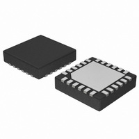
IC CLOCK/DATA DELAY 2CH 24-QFN
Manufacturer
ON Semiconductor
Type
Programmable Delay Chipr
Datasheet
1.NB6L295MNTXG.pdf
(14 pages)
Specifications of NB6L295MNG
Input
CML, LVDS, LVPECL
Output
CML
Frequency - Max
1.5GHz
Voltage - Supply
2.4 V ~ 3.6 V
Operating Temperature
-40°C ~ 85°C
Mounting Type
Surface Mount
Package / Case
24-TFQFN Exposed Pad
Frequency-max
1.5GHz
Function
Active Programmable Delay Line
Supply Voltage (min)
2.375 V
Maximum Operating Temperature
+ 85 C
Minimum Operating Temperature
- 40 C
Mounting Style
SMD/SMT
Supply Voltage (max)
3.6 V
Lead Free Status / RoHS Status
Lead free / RoHS Compliant
Available stocks
Company
Part Number
Manufacturer
Quantity
Price

Part Number:
NB6L295MNG
Manufacturer:
ON/安森美
Quantity:
20 000


Serial Data Interface Programming
11 SDATA bits are 1 PSEL bit, 1 MSEL bit and 9 delay value data bitsD[8:0]. A separate 11−bit load cycle is required to program
the delay data value of each channel, PD0 and PD1. For example, at powerup two load cycles will be needed to initially set
PD0 and PD1; Dual Mode Operation as shown in Figures 3 and 4 and Extended Mode Operation as shown in Figures 5 and 6.
Refer to Table 7, Channel and Mode Select BIT Functions. In a load cycle, the 11−Bit Shift Register least significant bit
(clocked in first) is PSEL and will determine which channel delay buffer, either PDO (LOW) or PD1 (HIGH), will latch the
delay data value D[8:0]. The MSEL BIT determines the Delay Mode. When set LOW, the Dual Delay Mode is selected and
the device uses both channels independently. A pulse edge entering IN0/IN0 is delayed according to the values in PD0 and exits
from Q0/Q0. An input signal pulse edge entering IN1/IN1 is delayed according to the values in PD1 and exits from Q1/Q1.
When MSEL is set HIGH, the Extended Delay Mode is selected and an input signal pulse edge enters IN0 and IN0 and flows
through PD0 and is extended through PD1 to exit at Q1 and Q1. The most significant 9−bits, D[8:0] are delay value data for
both channels. See Figure 7.
DUAL MODE OPERATIONS
(MSB)
EXTENDED MODE OPERATIONS
(MSB)
0/1
D8
0/1
D8
Table 7. CHANNEL AND MODE SELECT BIT FUNCTIONS
PSEL
MSEL
D[8:0]
The NB6L295 is programmed by loading the 11−Bit SHIFT REGISTER using the SCLK, SDATA and SLOAD inputs. The
BIT Name
0/1
D7
0/1
D7
PD0 Programmable Delay
PD0 Programmable Delay
0/1
0/1
D6
D6
0/1
0/1
D5
D5
Figure 3. PDO Shift Register
Figure 5. PDO Shift Register
0 Loads Data to PD0
1 Loads Data to PD1
0 Selects Dual Programmable Delay Paths, 3.1 ns to 8.8 ns Delay Range for Each Path
1 Selects Extended Delay Path from IN0/IN0 to Q1/Q1, 6.0 ns to 17.2 ns Delay Range; Disables Q0/Q0 Outputs,
Q0−LOW, Q0−HIGH.
Select one of 512 Delay Values
0/1
0/1
D4
D4
0/1
0/1
D3
D3
0/1
D2
0/1
D2
0/1
D1
0/1
D1
0/1
D0
0/1
D0
MSEL
MSEL
0
1
Control
Control
Bits
Bits
PSEL
PSEL
(LSB)
(LSB)
0
0
http://onsemi.com
Value
Bit
Name
Name
Value
Bit
Name
Name
8
(MSB)
(MSB)
0/1
D8
0/1
D8
Function
0/1
0/1
D7
D7
PD1 Programmable Delay
PD1 Programmable Delay
0/1
0/1
D6
D6
0/1
0/1
D5
D5
Figure 4. PD1 Shift Register
Figure 6. PD1 Shift Register
0/1
0/1
D4
D4
0/1
0/1
D3
D3
0/1
D2
0/1
D2
0/1
D1
0/1
D1
0/1
D0
0/1
D0
MSEL
MSEL
0
1
Control
Control
Bits
Bits
PSEL
PSEL
(LSB)
(LSB)
1
1
Value
Bit
Name
Name
Value
Bit
Name
Name
Related parts for NB6L295MNG
Image
Part Number
Description
Manufacturer
Datasheet
Request
R

Part Number:
Description:
Lvpecl Dual Programmable Delay
Manufacturer:
ON Semiconductor
Datasheet:
Part Number:
Description:
ON Semiconductor [VOLTAGE REGULATOR]
Manufacturer:
ON Semiconductor
Datasheet:
Part Number:
Description:
357-036-542-201 CARDEDGE 36POS DL .156 BLK LOPRO
Manufacturer:
ON Semiconductor
Datasheet:
Part Number:
Description:
357-036-542-201 CARDEDGE 36POS DL .156 BLK LOPRO
Manufacturer:
ON Semiconductor
Datasheet:
Part Number:
Description:
357-036-542-201 CARDEDGE 36POS DL .156 BLK LOPRO
Manufacturer:
ON Semiconductor
Datasheet:
Part Number:
Description:
357-036-542-201 CARDEDGE 36POS DL .156 BLK LOPRO
Manufacturer:
ON Semiconductor
Datasheet:
Part Number:
Description:
357-036-542-201 CARDEDGE 36POS DL .156 BLK LOPRO
Manufacturer:
ON Semiconductor
Datasheet:
Part Number:
Description:
357-036-542-201 CARDEDGE 36POS DL .156 BLK LOPRO
Manufacturer:
ON Semiconductor
Datasheet:
Part Number:
Description:
357-036-542-201 CARDEDGE 36POS DL .156 BLK LOPRO
Manufacturer:
ON Semiconductor
Datasheet:
Part Number:
Description:
357-036-542-201 CARDEDGE 36POS DL .156 BLK LOPRO
Manufacturer:
ON Semiconductor
Datasheet:
Part Number:
Description:
357-036-542-201 CARDEDGE 36POS DL .156 BLK LOPRO
Manufacturer:
ON Semiconductor
Datasheet:
Part Number:
Description:
357-036-542-201 CARDEDGE 36POS DL .156 BLK LOPRO
Manufacturer:
ON Semiconductor
Datasheet:
Part Number:
Description:
Manufacturer:
ON Semiconductor
Datasheet:
Part Number:
Description:
Manufacturer:
ON Semiconductor
Datasheet: