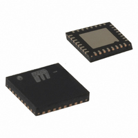
SY58032UMG Micrel Inc, SY58032UMG Datasheet - Page 8

SY58032UMG
Manufacturer Part Number
SY58032UMG
Description
IC BUFFER 1:8FANOUT LVPECL 32MLF
Manufacturer
Micrel Inc
Series
Precision Edge®r
Type
Fanout Buffer (Distribution)r
Datasheet
1.SY58032UMG.pdf
(9 pages)
Specifications of SY58032UMG
Number Of Circuits
1
Ratio - Input:output
1:8
Differential - Input:output
Yes/Yes
Input
CML, LVDS, LVPECL
Output
LVPECL
Frequency - Max
4GHz
Voltage - Supply
2.375 V ~ 3.6 V
Operating Temperature
-40°C ~ 85°C
Mounting Type
Surface Mount
Package / Case
32-MLF®, QFN
Frequency-max
4GHz
Number Of Outputs
16
Operating Supply Voltage (max)
3.6V
Operating Temp Range
-40C to 85C
Propagation Delay Time
0.33ns
Operating Supply Voltage (min)
2.375V
Mounting
Surface Mount
Pin Count
32
Operating Supply Voltage (typ)
2.5/3.3V
Package Type
MLF
Input Frequency
4GHz
Operating Temperature Classification
Industrial
Lead Free Status / RoHS Status
Lead free / RoHS Compliant
Other names
576-1389
Available stocks
Company
Part Number
Manufacturer
Quantity
Price
Company:
Part Number:
SY58032UMG
Manufacturer:
MICREL
Quantity:
39
Part Number:
SY58032UMG
Manufacturer:
MICREL
Quantity:
20 000
Micrel, Inc.
impedance (open emitter), and small signal swing which
results in low EMI. LVPECL is ideal for driving 50Ω and 100Ω
controlled impedance transmission lines. There are several
techniques for terminating the LVPECL output: Parallel
M9999-072810
hbwhelp@micrel.com or (408) 955-1690
Part Number
SY58031U
SY58032U
SY58033U
LVPECL OUTPUT
RELATED MICREL PRODUCTS AND SUPPORT DOCUMENTATION
LVPECL has high input impedance, and very low output
Function
Ultra-Precision 1:8 Fanout Buffer with 400mV CML
Outputs and Internal I/O Termination
Ultra-Precision 1:8 Fanout Buffer with LVPECL
Outputs and Internal Termination
Ultra-Precision 1:8 Fanout Buffer with 400mV LVPECL
Outputs and Internal Termination
32-MLF
Application Note
HBW Solutions
®
Manufacturing Guidelines Exposed Pad
“source”
Figure 4. Parallel Termination-Thevenin Equivalent
Notes:
1. Power-saving alternative to Thevenin termination.
2. Place termination resistors as close to destination inputs as possible.
3. R
4. For 2.5V systems, R
+3.3V
+3.3V
b
For +2.5V systems,
R1 = 250Ω, R2 = 62.5Ω
resistor sets the DC bias voltage, equal to V
Figure 5. Parallel Termination (3-Resistor)
Z
Z
O
O
= 50Ω
= 50Ω
Z = 50Ω
Z = 50Ω
b
= 19Ω, For 3.3V systems, R
130Ω
82Ω
R1
R2
50Ω
8
Termination-Thevenin Equivalent, Parallel Termination
(3-resistor), and AC-coupled Termination. Unused output
pairs may be left floating. However, single-ended outputs
must be terminated, or balanced.
+3.3V
Data Sheet Link
http://www.micrel.com/product-info/products/sy58031u.shtml
http://www.micrel.com/product-info/products/sy58032u.shtml
http://www.micrel.com/product-info/products/sy58033u.shtml
www.amkor.com/products/notes_papers/MLF_AppNote_0902.pdf
http://www.micrel.com/product-info/as/solutions.shtml
R
T
50Ω
.
b
R1
130Ω
R2
82Ω
b
= 50Ω
C1 (optional)
0.01µF
V
“destination”
+3.3V
T
= V
+3.3V
V
CC
CC
–2V
Precision Edge
SY58032U
®


