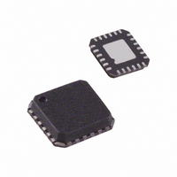
ADF4360-4BCPZ Analog Devices Inc, ADF4360-4BCPZ Datasheet - Page 2

ADF4360-4BCPZ
Manufacturer Part Number
ADF4360-4BCPZ
Description
IC INT SYNTH/VCO SEALED 24-LFCSP
Manufacturer
Analog Devices Inc
Type
Fanout Distribution, Integer N Synthesizer (RF)r
Datasheet
1.ADF4360-4BCPZ.pdf
(24 pages)
Specifications of ADF4360-4BCPZ
Pll
Yes
Input
CMOS
Output
Clock
Number Of Circuits
1
Ratio - Input:output
1:2
Differential - Input:output
No/No
Frequency - Max
1.75GHz
Divider/multiplier
Yes/No
Voltage - Supply
3 V ~ 3.6 V
Operating Temperature
-40°C ~ 85°C
Mounting Type
Surface Mount
Package / Case
24-LFCSP
Frequency-max
1.75GHz
Pll Type
Frequency Synthesis
Frequency
1.45GHz
Supply Current
10mA
Supply Voltage Range
3V To 3.6V
Digital Ic Case Style
LFCSP
No. Of Pins
24
Operating Temperature Range
0°C To +150°C
Lead Free Status / RoHS Status
Lead free / RoHS Compliant
For Use With
EVAL-ADF4360-4EBZ1 - BOARD EVALUATION FOR ADF4360-4
Lead Free Status / RoHS Status
Lead free / RoHS Compliant, Lead free / RoHS Compliant
Available stocks
Company
Part Number
Manufacturer
Quantity
Price
Part Number:
ADF4360-4BCPZ
Manufacturer:
ADI/亚德诺
Quantity:
20 000
Company:
Part Number:
ADF4360-4BCPZRL7
Manufacturer:
ELPIDA
Quantity:
147
Part Number:
ADF4360-4BCPZRL7
Manufacturer:
ADI/亚德诺
Quantity:
20 000
ADF4360-4
TABLE OF CONTENTS
Specifications..................................................................................... 3
Timing Characteristics..................................................................... 5
Absolute Maximum Ratings............................................................ 6
Pin Configuration and Functional Descriptions.......................... 7
Typical Performance Characteristics ............................................. 8
Circuit Description........................................................................... 9
REVISION HISTORY
12/04—Rev. 0 to Rev. A
Updated Format..................................................................Universal
Changes to Specifications ................................................................ 3
Changes to Timing Characteristics ................................................ 5
Changes to the Power-Up Section................................................ 16
Added Table 10 ............................................................................... 16
Added Figure 16.............................................................................. 16
Changes to Ordering Guide .......................................................... 23
Updated the Outline Dimensions................................................. 23
11/03—Revision 0: Initial Version
Transistor Count........................................................................... 6
ESD Caution.................................................................................. 6
Reference Input Section............................................................... 9
Prescaler (P/P + 1)........................................................................ 9
A and B Counters ......................................................................... 9
R Counter ...................................................................................... 9
PFD and Charge Pump................................................................ 9
MUXOUT and Lock Detect...................................................... 10
Input Shift Register..................................................................... 10
Rev. A | Page 2 of 24
Applications..................................................................................... 20
Outline Dimensions ....................................................................... 23
VCO ............................................................................................. 10
Output Stage................................................................................ 11
Latch Structure ........................................................................... 12
Power-Up..................................................................................... 16
Control Latch .............................................................................. 18
N Counter Latch......................................................................... 19
R Counter Latch ......................................................................... 19
Direct Conversion Modulator .................................................. 20
Fixed Frequency LO................................................................... 21
Interfacing ................................................................................... 21
PCB Design Guidelines for Chip Scale Package........................... 22
Output Matching ........................................................................ 22
Ordering Guide .......................................................................... 23


