NB4N441MNG ON Semiconductor, NB4N441MNG Datasheet - Page 7
NB4N441MNG
Manufacturer Part Number
NB4N441MNG
Description
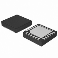
IC SYNTH PLL CLK LVPECL 24-QFN
Manufacturer
ON Semiconductor
Type
Clock/Frequency Synthesizerr
Datasheet
1.NB4N441MNR2G.pdf
(12 pages)
Specifications of NB4N441MNG
Pll
Yes
Input
LVCMOS, LVTTL, Crystal
Output
LVPECL
Number Of Circuits
1
Ratio - Input:output
1:1
Differential - Input:output
Yes/Yes
Frequency - Max
425MHz
Divider/multiplier
No/No
Voltage - Supply
3.135 V ~ 3.465 V
Operating Temperature
-40°C ~ 85°C
Mounting Type
Surface Mount
Package / Case
24-TFQFN Exposed Pad
Frequency-max
425MHz
Lead Free Status / RoHS Status
Lead free / RoHS Compliant
Available stocks
Company
Part Number
Manufacturer
Quantity
Price

Company:
Part Number:
NB4N441MNG
Manufacturer:
ON Semiconductor
Quantity:
4


General
generates a differential LVPECL clock output frequency
from 12.5 MHz to 425 MHz. A three−wire SPI interface is
used to configure the device to produce the exact frequency
of one of sixteen predefined popular standard protocol
output frequencies from a single 27 MHz crystal reference;
see Table 1. This serial interface gives the user complete
control of each internal counter/divider.
SPI interface can also enable the user to configure the device
for frequencies not specified in Table 1.
Input Clock / Crystal Functionality
27.000 MHz frequency source is required. This can be
accomplished by connecting a 27.000 MHz crystal across
the XTAL1 and XTAL2 pins. If driving single ended, use the
XTAL1 pin and leave XTAL2 floating. The CLK/XTAL1
input will accept a LVTTL/LVCMOS input.
Frequency Control Logic Configuration
divider for the PLL feedback path and a 3−bit Output
Divider, which divides the VCO frequency by 2, 4, 8, 16, or
32. The Frequency Control Logic for the NB4N441
configures these dividers and counters through the
Serial inputs and will select one of the sixteen
predetermined clock frequencies in Table 1. The serial
interface can also be used to configure the device for user
specified custom frequencies not specified in Table 1.
Output frequencies are generated based on the following
equation: F
that
400 MHz < VCO < 850 MHz with VCO = F
10 MHz < F
Output Enable
Disable/Enable pin, OE. The synchronous output enable pin
insures no runt clock pulses are generated. When disabled,
CLKOUT is set LOW and CLKOUT is set HIGH.
Table 8. Table 8. Output Enable Function
OE
The NB4N441 is a precision clock synthesizer which
If a different or custom output frequency is required, the
To generate the exact protocol frequencies in Table 1, a
The NB4N441 includes a 5−bit input prescaler, a 10−bit
The NB4N441 incorporates a synchronous output
1
0
the
OUT
xtal
< 28 MHz.
= (F
internal
CLKOUT = L, CLKOUT = H
xtal
Clock Outputs Disabled
Clock Outputs Enabled
/P) * M B N, with the stipulation
Function
VCO
frequency
APPLICATIONS INFORMATION
OUT
* N and
http://onsemi.com
NB4N441
be
7
Lock Detect Functionality
which indicates the locked status of the PLL. When the PLL
is locked, the LOCKED output pin asserts a logic Low.
When the internal phase lock is lost (such as when the input
clock stops, drifts beyond the pullable range of the crystal,
or suddenly shifts in phase), the LOCKED output goes High.
Using the On−Board Crystal Oscillator
crystal oscillator to minimize system implementation costs.
resonant. For exact tuning of cyrstal frequency, capacitors
should be connected from pins X1 and X2. Typical loading
should be on the order of 20 pF to 30 pF (on each crystal
input pin). As the oscillator is somewhat sensitive to loading
on its inputs, the user is advised to mount the crystal as close
to the NB4N441 as possible to avoid any board level
parasitic effects. To facilitate collocation, surface mount
crystals are recommended, but not required.
Table 9. Table 9. Lock Detect Function
Table 10. CRYSTAL SPECIFICATIONS
Crystal Cut
Resonance
Load Capacitance
Frequency Tolerance
Frequency/Temperature Stability
Operating Range
Shunt Capacitance
Equivalent Series Resistance (ESR)
Correlation Drive Level
Aging
The NB4N441 features a PLL Lock Detect function
The NB4N441 features a fully integrated on−board
The crystal should be fundamental mode, parallel
LOCKED
Parameter
0
1
PLL is not Locked
PLL is Locked
Fundamental AT Cut
Parallel Resonance
±20 ppm 0 to 70°C
±15 ppm at 25°C
Function
15 ppm /10 Yrs
(First 3 Years)
−40 to +85°C
0 to 70°C or
1.0 mW Max
5 ppm / Yr
50 W Max
5 pF Max
Value
18 pF
Related parts for NB4N441MNG
Image
Part Number
Description
Manufacturer
Datasheet
Request
R

Part Number:
Description:
3.3v Serial Input Multiprotocol Pll Clock Synthesizer, Differential Lvpecl Output
Manufacturer:
ON Semiconductor
Datasheet:
Part Number:
Description:
ON Semiconductor [VOLTAGE REGULATOR]
Manufacturer:
ON Semiconductor
Datasheet:
Part Number:
Description:
357-036-542-201 CARDEDGE 36POS DL .156 BLK LOPRO
Manufacturer:
ON Semiconductor
Datasheet:
Part Number:
Description:
357-036-542-201 CARDEDGE 36POS DL .156 BLK LOPRO
Manufacturer:
ON Semiconductor
Datasheet:
Part Number:
Description:
357-036-542-201 CARDEDGE 36POS DL .156 BLK LOPRO
Manufacturer:
ON Semiconductor
Datasheet:
Part Number:
Description:
357-036-542-201 CARDEDGE 36POS DL .156 BLK LOPRO
Manufacturer:
ON Semiconductor
Datasheet:
Part Number:
Description:
357-036-542-201 CARDEDGE 36POS DL .156 BLK LOPRO
Manufacturer:
ON Semiconductor
Datasheet:
Part Number:
Description:
357-036-542-201 CARDEDGE 36POS DL .156 BLK LOPRO
Manufacturer:
ON Semiconductor
Datasheet:
Part Number:
Description:
357-036-542-201 CARDEDGE 36POS DL .156 BLK LOPRO
Manufacturer:
ON Semiconductor
Datasheet:
Part Number:
Description:
357-036-542-201 CARDEDGE 36POS DL .156 BLK LOPRO
Manufacturer:
ON Semiconductor
Datasheet:
Part Number:
Description:
357-036-542-201 CARDEDGE 36POS DL .156 BLK LOPRO
Manufacturer:
ON Semiconductor
Datasheet:
Part Number:
Description:
357-036-542-201 CARDEDGE 36POS DL .156 BLK LOPRO
Manufacturer:
ON Semiconductor
Datasheet:
Part Number:
Description:
Manufacturer:
ON Semiconductor
Datasheet:
Part Number:
Description:
Manufacturer:
ON Semiconductor
Datasheet: