NB2669ASNR2 ON Semiconductor, NB2669ASNR2 Datasheet - Page 5
NB2669ASNR2
Manufacturer Part Number
NB2669ASNR2
Description
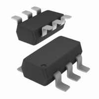
IC CLOCK SYNTHESIZR 4MA TSOT-6
Manufacturer
ON Semiconductor
Type
Clock/Frequency Synthesizerr
Datasheet
1.NB2669ASNR2.pdf
(8 pages)
Specifications of NB2669ASNR2
Pll
Yes
Input
CMOS
Output
CMOS
Number Of Circuits
1
Ratio - Input:output
1:1
Differential - Input:output
No/No
Frequency - Max
13MHz
Divider/multiplier
Yes/No
Voltage - Supply
2.375 V ~ 3.6 V
Operating Temperature
0°C ~ 70°C
Mounting Type
Surface Mount
Package / Case
SC-74-6
Frequency-max
13MHz
Lead Free Status / RoHS Status
Contains lead / RoHS non-compliant
Available stocks
Company
Part Number
Manufacturer
Quantity
Price

Company:
Part Number:
NB2669ASNR2G
Manufacturer:
TI
Quantity:
80


Table 6. DC ELECTRICAL CHARACTERISTICS FOR 3.3 V SUPPLY
temperature 25C)
NOTE: Device will meet the specifications after thermal equilibrium has been established when mounted in a test socket or printed circuit
4. XIN/CLKIN pin and PD pin are pulled low.
5. V
Table 7. AC ELECTRICAL CHARACTERISTICS FOR 3.3 V SUPPLY
NOTE: Device will meet the specifications after thermal equilibrium has been established when mounted in a test socket or printed circuit
6. t
V
V
I
I
I
I
V
V
I
I
V
t
Z
CLKIN
ModOUT
f
t
t
t
t
IL
IH
XOL
XOH
DD
CC
ON
d
LH
HL
JC
D
OUT
IL
IH
OL
OH
DD
LH
Symbol
Symbol
DD
(Note 6)
(Note 6)
and t
board with maintained transverse airflow greater than 500 lfpm. Electrical parameters are guaranteed only over the declared
operating temperature range. Functional operation of the device exceeding these conditions is not implied. Device specification limit
values are applied individually under normal operating conditions and not valid simultaneously.
and CLKIN input are stable, PD pin is made high from low.
HL
are measured at capacitive load of 15 pF.
Input LOW Voltage
Input HIGH Voltage
Input LOW Current
Input HIGH Current
XOUT Output LOW Current (@ 0.4 V, V
XOUT Output HIGH Current (@ 2.5 V, V
Output LOW Voltage (V
Output HIGH Voltage (V
Static Supply Current (Note 4)
Dynamic Supply Current (3.3 V, 10 MHz, and No Load)
Operating Voltage
PLL first locked cycle time (Note 5)
Clock Output Impedance
Input Frequency
Output Frequency
Frequency Deviation
Output Rise Time (measured at 0.8 V to 2.0 V)
Output Fall Time (measured at 2.0 V to 0.8 V)
Jitter (Cycle--to--Cycle)
Output Duty Cycle
DD
DD
Description
Description
= 3.3 V, I
= 3.3 V, I
OL
Input Frequency = 6.0 MHz
OH
Input Frequency = 13 MHz
= 8.0 mA)
DD
= 8.0 mA)
DD
http://onsemi.com
= 3.3 V)
= 3.3 V)
5
(Test Conditions: All parameters are measured at room
GND -- 0.3
Min
Min
2.0
2.5
2.7
0.5
0.4
45
6
6
Typ
Typ
3.0
3.0
2.5
3.3
1.3
0.9
45
50
V
DD
1.48
0.74
Max
Max
200
--35
0.8
0.4
3.6
5.0
1.5
1.1
35
10
13
13
55
+ 0.3
MHz
MHz
Unit
Unit
mA
mA
mA
mS
mA
mA
mA
ns
ns
ps
%
%
Ω
V
V
V
V
V
Related parts for NB2669ASNR2
Image
Part Number
Description
Manufacturer
Datasheet
Request
R

Part Number:
Description:
Low Power, Reduced Emi Clock Synthesizer
Manufacturer:
ON Semiconductor
Datasheet:
Part Number:
Description:
ON Semiconductor [VOLTAGE REGULATOR]
Manufacturer:
ON Semiconductor
Datasheet:
Part Number:
Description:
357-036-542-201 CARDEDGE 36POS DL .156 BLK LOPRO
Manufacturer:
ON Semiconductor
Datasheet:
Part Number:
Description:
357-036-542-201 CARDEDGE 36POS DL .156 BLK LOPRO
Manufacturer:
ON Semiconductor
Datasheet:
Part Number:
Description:
357-036-542-201 CARDEDGE 36POS DL .156 BLK LOPRO
Manufacturer:
ON Semiconductor
Datasheet:
Part Number:
Description:
357-036-542-201 CARDEDGE 36POS DL .156 BLK LOPRO
Manufacturer:
ON Semiconductor
Datasheet:
Part Number:
Description:
357-036-542-201 CARDEDGE 36POS DL .156 BLK LOPRO
Manufacturer:
ON Semiconductor
Datasheet:
Part Number:
Description:
357-036-542-201 CARDEDGE 36POS DL .156 BLK LOPRO
Manufacturer:
ON Semiconductor
Datasheet:
Part Number:
Description:
357-036-542-201 CARDEDGE 36POS DL .156 BLK LOPRO
Manufacturer:
ON Semiconductor
Datasheet:
Part Number:
Description:
357-036-542-201 CARDEDGE 36POS DL .156 BLK LOPRO
Manufacturer:
ON Semiconductor
Datasheet:
Part Number:
Description:
357-036-542-201 CARDEDGE 36POS DL .156 BLK LOPRO
Manufacturer:
ON Semiconductor
Datasheet:
Part Number:
Description:
357-036-542-201 CARDEDGE 36POS DL .156 BLK LOPRO
Manufacturer:
ON Semiconductor
Datasheet:
Part Number:
Description:
Manufacturer:
ON Semiconductor
Datasheet:
Part Number:
Description:
Manufacturer:
ON Semiconductor
Datasheet: