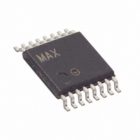
DS1123LE-25+ Maxim Integrated Products, DS1123LE-25+ Datasheet - Page 11

DS1123LE-25+
Manufacturer Part Number
DS1123LE-25+
Description
IC TIMING ELEMENT PROG 16-TSSOP
Manufacturer
Maxim Integrated Products
Datasheet
1.DS1123LE-200.pdf
(14 pages)
Specifications of DS1123LE-25+
Number Of Taps/steps
256
Function
Programmable
Delay To 1st Tap
16.5nS
Tap Increment
0.25nS
Available Total Delays
63.75ns
Voltage - Supply
3 V ~ 3.6 V
Operating Temperature
0°C ~ 70°C
Mounting Type
Surface Mount
Package / Case
16-TSSOP
Lead Free Status / RoHS Status
Lead free / RoHS Compliant
Number Of Independent Delays
-
to be shifted to U2, U2’s data would be shifted to U3, etc.
As shown, the microprocessor would have to shift 24 bits
during each read or write cycle to avoid inadvertently
changing the settings in any of the 3-wire devices. Also
note that the feedback resistor or a separate input (not
shown) can still be used to read the 3-wire device set-
tings when multiple devices are cascaded.
To use the DS1123L as a delay line, the MS pin must
be tied to ground. When used as a delay line, the inter-
nal architecture of the DS1123L allows the output delay
time to be considerably longer than the input pulse
width (see AC specifications). This feature is useful in
many applications, in particular in clock phase control,
where delays up to and beyond one full clock period
can be achieved. Table 1 lists some of the delay char-
acteristics of the different speed options available for
the DS1123L device.
All delay lines have an inherent step-zero delay
between IN and OUT (t
delay through the input and output buffers. To simplify
system design, a reference delay has been included on
Figure 6. Serial Interface Timing Diagram
Configuring the DS1123L as a Delay Line
ENABLE
CLOCK
3.3V, 8-Bit, Programmable Timing Element
SERIAL
SERIAL
DELAY
INPUT
INPUT
(CLK)
TIME
(LE)
(D)
(Q)
Using the Reference Delay
D0
) due to the propagation
t
EGV
t
DSC
t
ES
____________________________________________________________________
PREVIOUS VALUE
NEW
BIT 7
OLD BIT 7
t
CQV
t
CW
t
DHC
NEW BIT 6
OLD BIT 6
t
CW
t
EW
the DS1123L that can be used to compensate for the
step-zero delay. The reference output allows the
DS1123L to be used to generate small differential
delays that cannot be generated when the OUT delay
is referenced to the input. The step-zero OUT delay is
always approximately 1ns faster than the REF delay
(see Figure 8). This allows the DS1123L to generate a
nondelayed output with respect to the reference output.
In addition, the reference output driver is sized similarly
to the OUT output driver, both outputs act similarly over
temperature, and they are both triggered at the same
time regardless of the exact input threshold. These fea-
tures make the output delay with respect to the refer-
ence act more ideally because both of these outputs
are skewed approximately the same amount due to
these phenomena.
Integral nonlinearity (INL) is defined as the deviation from
a straight line response drawn between the measured
step-zero delay and the measured step 255 delay with
respect to the reference output. INL measured with
respect to IN is not specified, but should be slightly high-
er than when measured with respect to the reference out-
put. This is because measurements taken with respect to
t
CQX
OLD BIT 0
BIT 0
NEW
t
EH
t
EDX
Integral Nonlinearity
t
t
EQZ
EDZ
VALUE
NEW
11


