1469054-1 TE Connectivity, 1469054-1 Datasheet - Page 3
1469054-1
Manufacturer Part Number
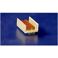
1469054-1
Description
HM-ZD 2PR HDR SELECT LOAD
Manufacturer
TE Connectivity
Specifications of 1469054-1
Product Type
Connector
Connector Type
Header
Pcb Mounting Orientation
Vertical
Shield Material
Phosphor bronze
Module Length (mm [in])
24.90 [0.980]
Interface Type
HM-Zd
Termination Method
Press Fit
Termination End Plating
Tin-Lead over Nickel
Card Slot Pitch (mm [in])
20.3 [0.8]
Columns Per Connector
10
Centerline (mm [in])
2.50 [0.098]
Selectively Loaded
Yes
Number Of Positions
32
Contact Type
Pin
Contact Termination Type
Through Hole
Contact Configuration
ACTION PIN Post
Feedthrough Post Length (mm [in])
2.50 [0.098]
Contact Mating Area Length (mm [in])
6.35 [0.250]
Contact Base Material
Phosphor Bronze
Housing Material
Polyester GF
Number Of Pairs Per Column
2
Number Of Pairs Per Connector
20
Sequenced Pins
Yes (See Drawing)
Advancedtca Specified Product
No
Rohs/elv Compliance
RoHS compliant, ELV compliant
Lead Free Solder Processes
Not relevant for lead free process
Rohs/elv Compliance History
Always was RoHS compliant


Rev C
W ithstanding voltage.
Tem perature rise vs current.
Vibration, random .
Mechanical shock.
Durability.
Mating force.
Unm ating force.
Test Description
1 m inute hold with no breakdown or
flashover.
30°C m axim um tem perature rise at
.7 am pere per contact, fully
energized.
No discontinuities of 1 m icrosecond
or longer duration.
See Note.
No discontinuities of 1 m icrosecond
or longer duration.
See Note.
See Note.
0.38 N [.085 lbf] m axim um average
per m ated contact. “m ated contact”
refers to signal pins and ground
blades, i.e., each signal pin = 1
contact and each ground blade = 1
contact.
0.15 N [.03 lbf] m inim um average
per contact (applies to both signal
and ground contacts).
Figure 1 (continued)
MECHANICAL
Requirem ent
EIA-364-20, Condition I.
650 volts AC at sea level between
m ated pairs of signal contacts.
550 volts AC at sea level between
m ated ground and signal contacts.
Test between adjacent signal
contacts, and closest signal and
ground contact.
EIA-364-70, Method 1.
Stabilize at a single current level
until 3 readings at 5 m inute
intervals are within 1°C.
EIA-364-28, Test Condition VII,
Condition D.
Subject m ated specim ens to 3.10
G's rm s between 20-500 Hz. 15
m inutes in each of 3 m utually
perpendicular planes.
See Figure 4.
EIA-364-27, Method A.
Subject m ated specim ens to
490m /s (50 G's) half-sine shock
pulses of 11 m illiseconds duration.
3 shocks in each direction applied
along 3 m utually perpendicular
planes, 18 total shocks.
See Figure 4.
EIA-364-9.
Mate and unm ate specim ens for
250 cycles at a m axim um rate of
600 cycles per hour.
EIA-364-13.
Measure force necessary to m ate
specim ens at a m axim um rate of
12.7 m m [.5 in] per m inute.
EIA-364-13.
Measure force necessary to
unm ate specim ens at a m axim um
rate of 12.7 m m [.5 in] per m inute.
2
Procedure
108-2055
3 of 8
Related parts for 1469054-1
Image
Part Number
Description
Manufacturer
Datasheet
Request
R


Part Number:
Description:
High Speed / Modular Connectors 30P HEADER ASSY
Manufacturer:
TE Connectivity
Datasheet:

Part Number:
Description:
High Speed / Modular Connectors REC 6X005P R/A LT B-PLANE HS3
Manufacturer:
TE Connectivity
Datasheet:

Part Number:
Description:
High Speed / Modular Connectors 2MM HM RCPT 50P R/A AU
Manufacturer:
TE Connectivity
Datasheet:

Part Number:
Description:
High Speed / Modular Connectors 2MM HM RCPT 50P R/A AU
Manufacturer:
TE Connectivity
Datasheet:


Part Number:
Description:
Manufacturer:
TE Connectivity
Datasheet:


Part Number:
Description:
Manufacturer:
TE Connectivity
Datasheet:

Part Number:
Description:
Manufacturer:
TE Connectivity
Datasheet:

Part Number:
Description:
Manufacturer:
TE Connectivity
Datasheet: