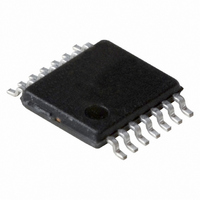
PCF2123TS/1,118 NXP Semiconductors, PCF2123TS/1,118 Datasheet - Page 23

PCF2123TS/1,118
Manufacturer Part Number
PCF2123TS/1,118
Description
IC SPI RTC/CALENDAR 14TSSOP
Manufacturer
NXP Semiconductors
Type
Clock/Calendar/Alarmr
Specifications of PCF2123TS/1,118
Package / Case
14-TSSOP
Time Format
HH:MM:SS (12/24 hr)
Date Format
YY-MM-DD-dd
Interface
SPI, 3-Wire Serial
Voltage - Supply
1.1 V ~ 5.5 V
Operating Temperature
-40°C ~ 85°C
Mounting Type
Surface Mount
Function
Clock/Calendar
Supply Voltage (max)
5.5 V
Supply Voltage (min)
1.1 V
Maximum Operating Temperature
+ 85 C
Minimum Operating Temperature
- 40 C
Mounting Style
SMD/SMT
Rtc Bus Interface
Serial (3-Wire, SPI)
Lead Free Status / RoHS Status
Lead free / RoHS Compliant
Memory Size
-
Lead Free Status / Rohs Status
Lead free / RoHS Compliant
Other names
568-4534-2
935286384118
PCF2123TS/1-T
935286384118
PCF2123TS/1-T
Available stocks
Company
Part Number
Manufacturer
Quantity
Price
Company:
Part Number:
PCF2123TS/1,118
Manufacturer:
VISHAY
Quantity:
15 160
Part Number:
PCF2123TS/1,118
Manufacturer:
NXP/恩智浦
Quantity:
20 000
NXP Semiconductors
PCF2123
Product data sheet
8.6.4 Countdown timer function
The 8-bit countdown timer at address 0Fh is controlled by the register Timer_clkout at
address 0Eh. The register Timer_clkout selects one of 4 source clock frequencies for the
timer (4.096 kHz, 64 Hz, 1 Hz, or
Table 28.
[1]
[2]
Remark: Note that all timings which are generated from the 32.768 kHz oscillator are
based on the assumption that there is 0 ppm deviation. Deviation in oscillator frequency
will result in deviation in timings. This is not applicable to interface timing.
The timer counts down from a software-loaded 8-bit binary value, n. Loading the counter
with 0 stops the timer. Values from 1 to 255 are valid. When the counter reaches 1, the
countdown timer flag (bit TF) will be set and the counter automatically re-loads and starts
the next timer period. Reading the timer will return the current value of the countdown
counter (see
If a new value of n is written before the end of the current timer period, then this value will
take immediate effect. NXP does not recommend changing n without first disabling the
counter (by setting bit TE = 0). The update of n is asynchronous to the timer clock,
CTD[1:0]
00
01
10
11
Fig 15. General countdown timer behavior
countdown value, n
countdown counter
timer source clock
When not in use, CTD must be set to
Time periods can be affected by correction pulses.
In this example it is assumed that the timer flag is cleared before the next countdown period
expires and that the pin INT is set to pulsed mode.
Bits CTD0 and CTD1 for timer frequency selection and countdown timer
durations
Timer source clock
frequency
4.096 kHz
64 Hz
1 Hz
1
60
Figure
INT
TE
TF
Hz
[2]
All information provided in this document is subject to legal disclaimers.
[2]
xx
xx
15).
[1]
Rev. 4 — 22 December 2010
03
03
Delay
Minimum timer duration
n = 1
244 s
15.625 ms
1 s
60 s
1
1
60
60
Hz for power saving.
Hz) and enables or disables the timer.
02
duration of first timer period after
enable may range from n − 1 to n + 1
01
03
02
n
SPI Real time clock/calendar
Maximum timer duration
n = 255
62.256 ms
3.984 s
255 s
4 h 15 min
01
03
PCF2123
© NXP B.V. 2010. All rights reserved.
02
n
01
001aaf906
23 of 61
03


