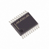
DS1306EN+ Maxim Integrated Products, DS1306EN+ Datasheet - Page 3

DS1306EN+
Manufacturer Part Number
DS1306EN+
Description
IC RTC SERIAL ALARM IND 20-TSSOP
Manufacturer
Maxim Integrated Products
Type
Clock/Calendar/Alarmr
Datasheet
1.DS1306E.pdf
(22 pages)
Specifications of DS1306EN+
Memory Size
96B
Time Format
HH:MM:SS (12/24 hr)
Date Format
YY-MM-DD-dd
Interface
SPI, 3-Wire Serial
Voltage - Supply
2 V ~ 5.5 V
Operating Temperature
-40°C ~ 85°C
Mounting Type
Surface Mount
Package / Case
20-TSSOP
Function
Clock/Calendar/Alarm
Rtc Memory Size
96 Byte
Supply Voltage (max)
5.5 V
Supply Voltage (min)
2 V
Maximum Operating Temperature
+ 85 C
Minimum Operating Temperature
- 40 C
Mounting Style
SMD/SMT
Rtc Bus Interface
Serial (3-Wire, SPI)
Lead Free Status / RoHS Status
Lead free / RoHS Compliant
PIN DESCRIPTION (continued)
4, 6, 13,
TSSOP
10
11
12
14
15
16
17
18
20
19
9
PIN
DIP
10
11
12
13
14
15
16
—
7
8
9
SERMODE
NAME
32kHz
SCLK
GND
V
SDO
V
N.C.
1Hz
SDI
CE
CCIF
CC1
1Hz Output. The 1Hz pin provides a 1Hz square wave output. This output
is active when the 1 Hz bit in the control register is a logic 1. Both INT0 and
1Hz pins are open-drain outputs. The interrupt, 1Hz signal, and the internal
clock continue to run regardless of the level of V
source is present).
Ground
Serial Interface Mode. The SERMODE pin offers the flexibility to choose
between two serial interface modes. When connected to GND, standard
3-wire communication is selected. When connected to V
communication is selected.
Chip Enable. The chip enable signal must be asserted high during a read or
a write for both 3-wire and SPI communication. This pin has an internal
55k pulldown resistor (typical).
Serial Clock. SCLK is used to synchronize data movement on the serial
interface for either the SPI or 3-wire interface.
Serial Data In. When SPI communication is selected, the SDI pin is the
serial data input for the SPI bus. When 3-wire communication is selected,
this pin must be tied to the SDO pin (the SDI and SDO pins function as a
single I/O pin when tied together).
Serial Data Out. When SPI communication is selected, the SDO pin is the
serial data output for the SPI bus. When 3-wire communication is selected,
this pin must be tied to the SDI pin (the SDI and SDO pins function as a
single I/O pin when tied together). V
Interface Logic Power-Supply Input. The V
drive SDO and 32kHz output pins to a level that is compatible with the
interface logic, thus allowing an easy interface to 3V logic in mixed supply
systems. This pin is physically connected to the source connection of the
p-channel transistors in the output buffers of the SDO and 32kHz pins.
32.768kHz Output. The 32kHz pin provides a 32.768kHz output. This
signal is always present. V
Primary Power Supply. DC power is provided to the device on this pin.
V
No Connection
CC1
is the primary power supply.
3 of 22
CCIF
provides the logic-high level.
FUNCTION
CCIF
provides the logic-high level.
CCIF
CC
pin allows the DS1306 to
(as long as a power
CC
, SPI


