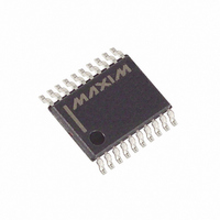
DS1306EN+ Maxim Integrated Products, DS1306EN+ Datasheet - Page 4

DS1306EN+
Manufacturer Part Number
DS1306EN+
Description
IC RTC SERIAL ALARM IND 20-TSSOP
Manufacturer
Maxim Integrated Products
Type
Clock/Calendar/Alarmr
Datasheet
1.DS1306E.pdf
(22 pages)
Specifications of DS1306EN+
Memory Size
96B
Time Format
HH:MM:SS (12/24 hr)
Date Format
YY-MM-DD-dd
Interface
SPI, 3-Wire Serial
Voltage - Supply
2 V ~ 5.5 V
Operating Temperature
-40°C ~ 85°C
Mounting Type
Surface Mount
Package / Case
20-TSSOP
Function
Clock/Calendar/Alarm
Rtc Memory Size
96 Byte
Supply Voltage (max)
5.5 V
Supply Voltage (min)
2 V
Maximum Operating Temperature
+ 85 C
Minimum Operating Temperature
- 40 C
Mounting Style
SMD/SMT
Rtc Bus Interface
Serial (3-Wire, SPI)
Lead Free Status / RoHS Status
Lead free / RoHS Compliant
DS1306
DESCRIPTION
The DS1306 serial alarm real-time clock (RTC) provides a full binary coded decimal (BCD) clock
calendar that is accessed by a simple serial interface. The clock/calendar provides seconds, minutes,
hours, day, date, month, and year information. The end of the month date is automatically adjusted for
months with fewer than 31 days, including corrections for leap year. The clock operates in either the 24-
hour or 12-hour format with AM/PM indicator. In addition, 96 bytes of NV RAM are provided for data
storage.
An interface logic power-supply input pin (V
) allows the DS1306 to drive SDO and 32kHz pins to a
CCIF
level that is compatible with the interface logic. This allows an easy interface to 3V logic in mixed supply
systems. The DS1306 offers dual-power supplies as well as a battery-input pin. The dual-power supplies
support a programmable trickle charge circuit that allows a rechargeable energy source (such as a super
cap or rechargeable battery) to be used for a backup supply. The V
pin allows the device to be backed
BAT
up by a non-rechargeable battery. The DS1306 is fully operational from 2.0V to 5.5V.
Two programmable time-of-day alarms are provided by the DS1306. Each alarm can generate an
interrupt on a programmable combination of seconds, minutes, hours, and day. “Don’t care” states can be
inserted into one or more fields if it is desired for them to be ignored for the alarm condition. A 1Hz and a
32kHz clock output are also available.
The DS1306 supports a direct interface to SPI serial data ports or standard 3-wire interface. An easy-to-
use address and data format is implemented in which data transfers can occur 1 byte at a time or in
multiple-byte burst mode.
OPERATION
The block diagram in Figure 1 shows the main elements of the serial alarm RTC. The following
paragraphs describe the function of each pin.
Figure 1. BLOCK DIAGRAM
1Hz
4 of 22


