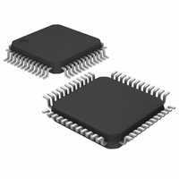
DS1558W+ Maxim Integrated Products, DS1558W+ Datasheet - Page 4

DS1558W+
Manufacturer Part Number
DS1558W+
Description
IC RTC W/NV RAM 3.3V 48-LQFP
Manufacturer
Maxim Integrated Products
Type
Watchdog Timer/NVSRAMr
Datasheet
1.DS1558W.pdf
(18 pages)
Specifications of DS1558W+
Time Format
HH:MM:SS (24 hr)
Date Format
YY-MM-DD-dd
Interface
Parallel
Voltage - Supply
3 V ~ 3.6 V
Operating Temperature
-40°C ~ 85°C
Mounting Type
Surface Mount
Package / Case
48-LQFP
Lead Free Status / RoHS Status
Lead free / RoHS Compliant
Memory Size
-
D
The D
alarm, watchdog timer, power-on reset, battery monitor, and NV SRAM controller. User access to all
registers within the DS1558 is accomplished with a byte-wide interface as shown in Figure 1. The RTC
registers contain century, year, month, date, day, hours, minutes, and seconds data in 24-hour BCD
fo
The DS1558 maps the RTC registers into the SRAM address space and constantly monitors A0–A18.
W n any
S
w
address lines on the DS1558 are connected to V
The RTC registers are double-buffered into an internal and external set. The user has direct access to the
external set. Clock/calendar updates to the external set of registers can be disabled and enabled to allow
th
continuously updated; this occurs regardless of external register settings to guarantee that accurate RTC
in
The DS1558 has interrupt (
The
m
th
system
monitored and an interrupt or reset output are activated if the correct activity is not detected within
programm
and hold the CPU
for this function.
T
and SRAM against out-of-tolerance V
enters an out-of-tolerance condition. W
s
data security during unpredictable
witc
RA
he
ith
e u
form
atc
e s
ES
rm
he
DS155 also
h use
at. Corrections for day of month and leap year are made automatically.
M, an
ser to
IRQ
ystem
hed
SRA
CR
S1
ation is always maintained.
wake-up. The
/
558 i a full-functio
on to s
FT in
r-pro
IPTI
Ms
ed lim ts. The DS1558 power-on reset can be used to detect a system p
d re
acc
of
8
sup
up
the
dir
ess static data. Assuming the internal oscillator is turned on, the internal set of registers is
s
grammed alarm values. The interrupt is always available while the device is powered from
ter
ply, and it can be programmed to occur when in the battery-backed state to serve as a
ON
u
i
ects reads and writes to the RTC registers within the DS1558. The
pply energy to the clock and the external SRAM. This feature pr
rupt output can be used to generate an external in
to 524,272
contains its own power-fail circuitry, which automatically pro
upper 16 address locations are accessed, the DS1558 inhibits
in a safe reset state until normal power returns and stabilizes
IRQ
/FT output can also be used as a CPU watchdog timer. CPU activity is
IRQ
addresses. Smaller SRAMs can be used, provided that the unused upper
n, year 2000-compliant (Y2KC), real-time clock/calendar with an RTC
/FT) and reset (
system operation brought on by low V
CCI
hen V
conditions by inhibiting the
CCI
CC
RST
.
4 of 18
goes below the level of V
) outputs that can be used to control CPU activity.
terrupt when the RTC register values
CC
CE
levels.
input when the V
BA
tects the data in the clock
T
; the
, the external battery is
ovides a high degree of
CER
ower-down or failure
DS1558 can be used
RST
and
output is used
OER
CC
supply
to the


