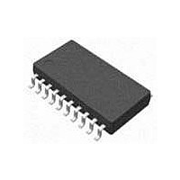
M41ST87WSS6F STMicroelectronics, M41ST87WSS6F Datasheet - Page 19

M41ST87WSS6F
Manufacturer Part Number
M41ST87WSS6F
Description
IC SUPERVISOR RTC/NVRAM 20-SSOP
Manufacturer
STMicroelectronics
Type
Clock/Calendar/Supervisorr
Specifications of M41ST87WSS6F
Memory Size
160B
Time Format
HH:MM:SS:hh (24 hr)
Date Format
YY-MM-DD-dd
Interface
I²C, 2-Wire Serial
Voltage - Supply
2.7 V ~ 3.6 V
Operating Temperature
-40°C ~ 85°C
Mounting Type
Surface Mount
Package / Case
20-SSOP
Function
Clock, Timestamp, Timekeeper, Watchdog, Alarm, Calendar, Timer, Timer Interrupt
Rtc Memory Size
1280 bit
Supply Voltage (max)
3.6 V
Supply Voltage (min)
2.7 V
Maximum Operating Temperature
+ 85 C
Minimum Operating Temperature
- 40 C
Mounting Style
SMD/SMT
Rtc Bus Interface
Serial
Supply Current
500 nA
Clock Format
Ss
Clock Ic Type
RTC
Interface Type
I2C
Memory Configuration
128 X 8
Supply Voltage Range
2.7V To 3.6V
Rohs Compliant
Yes
Lead Free Status / RoHS Status
Lead free / RoHS Compliant
Other names
497-10616-2
Available stocks
Company
Part Number
Manufacturer
Quantity
Price
Company:
Part Number:
M41ST87WSS6F
Manufacturer:
FSC
Quantity:
6 000
Part Number:
M41ST87WSS6F
Manufacturer:
ST
Quantity:
20 000
M41ST87Y, M41ST87W
2.6.2
2.6.3
Note:
2.6.4
2.6.5
Tamper bits (TB1 and TB2)
If the TEB
“Read-only” and is reset only by setting the TEB
register 0Fh.
Tamper interrupt enable bits (TIE1 and TIE2)
If this bit is set to a logic '1,' the IRQ/OUT pin will be activated when a tamper event occurs.
This function is also valid in battery backup if the ABE bit (alarm in battery backup) is also
set to '1' (see
In order to avoid an inadvertent activation of the IRQ/OUT pin due to a prior tamper event,
the flag register (0Fh) should be read prior to clearing and again setting the TEB
Tamper connect mode bit (TCM1 and TCM2)
This bit indicates whether the position of the external switch selected by the user is in the
normally open (TCM
page 20
Tamper polarity mode bits (TPM1 and TPM2)
The state of this bit indicates whether the tamper pin input will be taken high (to V
TPM
and
Figure 16 on page
X
= '1') or low (to V
and
X
bit is set, and a tamper condition occurs, the TB
Figure 16 on page
Figure 15 on page
X
= '1') or normally closed (TCM
SS
21).
if TPM
Doc ID 9497 Rev 9
21).
X
21).
= '0') to trigger a tamper event (see
X
bit to '0.' These bits are located in the flags
X
= '0') position (see
X
bit will be set to '1.' This bit is
Figure 14 on page 20
Operating modes
Figure 14 on
X
OUT
bit.
if
19/54


