2-5499206-1 TE Connectivity, 2-5499206-1 Datasheet - Page 3
2-5499206-1
Manufacturer Part Number
2-5499206-1
Description
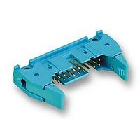
A/L UNIV HDR 10P VERT LG LAT BLUE
Manufacturer
TE Connectivity
Series
AMP-LATCHr
Datasheet
1.1761681-9.pdf
(5 pages)
Specifications of 2-5499206-1
Connector Type
Wire To Board
Contact Termination
Through Hole
Gender
Header
No. Of Contacts
10
No. Of Rows
2
Pitch Spacing
2.54mm
Contact Plating
Gold
Contact Material
Beryllium
Rohs Compliant
Yes
Product Type
Headers - Latch / Eject
Contact Gender
Pin (Male)
Pitch
2.54 mm
Number Of Positions / Contacts
10
Number Of Rows
2
Mounting Style
Through Hole
Termination Style
Crimp
Housing Material
Thermoplastic, Glass Filled
Product Line
AMP-LATCH
Profile
Standard
Pcb Mounting Orientation
Vertical
Pcb Mount Retention
Without
Mating Connector Lock
With
Housing Style
4-Sided
Ejection Latches
With
Post Size (mm [in])
0.64 [.025]
Latch Type
Long
Mating Connector Lock Type
Latch
Termination Post Length (mm [in])
2.79 [0.110]
Header Type
Universal Ejection Pin Headers
Number Of Positions
10
Centerline, Matrix (mm [in])
2.54 x 2.54 [.100 x .100]
Preloaded
Yes
Contact Plating, Mating Area, Material
Gold (30)
Contact Base Material
Phosphor Bronze
Connector Style
Header - Pin
Mating Alignment Type
Center
Mating Alignment
With
Ul Flammability Rating
UL 94V-0
Housing Color
Blue
Rohs/elv Compliance
RoHS compliant, ELV compliant
Lead Free Solder Processes
Wave solder capable to 240°C, Wave solder capable to 260°C, Wave solder capable to 265°C
Rohs/elv Compliance History
Always was RoHS compliant
Operating Temperature (°c)
-55 – +125
Temperature Rating
Standard
Lead Free Status / Rohs Status
Details


3.6.
Therm al shock.
Hum idity/tem perature cycling.
Rev F
NOTE
Product Qualification and Requalification Test Sequence
NOTE
Test Description
Shall meet visual requirements, show no physical damage and shall meet requirements of
additional tests as specified in Test Sequence in Figure 2.
(a)
(b)
See paragraph 4.1.A.
Numbers indicate sequence in which tests are performed.
Exam ination of product
Insulation resistance
W ithstanding voltage
Solderability
Com ponent resistance to wave soldering
Contact retention
Therm al shock
Hum idity/tem perature cycling
Test or Exam ination
See Note.
See Note.
ENVIRONMENTAL
Figure 1 (end)
Requirem ent
Figure 2
1,3,5
Test Sequence (b)
2
1
4
Test Group (a)
EIA-364-32, Test Condition II.
Subject unm ated specim ens to 5
cycles between -65 and 105°C with
30 m inute dwells at tem perature
extrem es.
EIA-364-31, Method III.
Subject unm ated specim ens to 10
cycles (10 days) between 25 and
65°C at 80 to 100% RH with cold
shock.
1,3
2
2
1,8
2,6
3,7
3
4
5
Procedure
108-40018
3 of 5
Related parts for 2-5499206-1
Image
Part Number
Description
Manufacturer
Datasheet
Request
R

Part Number:
Description:
High Speed / Modular Connectors HDI RECP ASSY 3 ROW 1197
Manufacturer:
TE Connectivity
Datasheet:

Part Number:
Description:
Conn Socket Strip RCP 54 POS 2.54mm Solder ST Thru-Hole
Manufacturer:
Tyco Electronics
Datasheet:
Part Number:
Description:
HDI PIN ASSY 3 ROW 54 POS
Manufacturer:
Tyco Electronics
Datasheet:

Part Number:
Description:
54 MODII HDR DRST UNSHRD STKG
Manufacturer:
TE Connectivity
Datasheet:

Part Number:
Description:
CONN HEADER 54POS DL .100 15GOLD
Manufacturer:
Tyco Electronics
Datasheet:

Part Number:
Description:
RES 220 OHM 1W 5% 2512
Manufacturer:
TE Connectivity
Datasheet:

Part Number:
Description:
Manufacturer:
TE Connectivity
Datasheet:

Part Number:
Description:
CONNECTOR, 5WAY, R/A, 2
Manufacturer:
TE Connectivity
Datasheet:

Part Number:
Description:
WIRE-BOARD CONN RECEPTACLE 10POS, 1.27MM
Manufacturer:
TE Connectivity
Datasheet:
Part Number:
Description:
INDUCTOR 680NH 500MA 1812
Manufacturer:
TE Connectivity
Datasheet:

Part Number:
Description:
Manufacturer:
TE Connectivity
Datasheet:

Part Number:
Description:
Manufacturer:
TE Connectivity
Datasheet:


Part Number:
Description:
WIRE-BOARD CONN, HEADER, 14POS, 2.54MM
Manufacturer:
TE Connectivity
Datasheet:

Part Number:
Description:
Conn Shrouded Header HDR 14 POS 2.54mm Solder ST Thru-Hole
Manufacturer:
TE Connectivity
Datasheet: