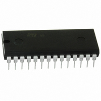
M48T59Y-70PC1 STMicroelectronics, M48T59Y-70PC1 Datasheet - Page 16

M48T59Y-70PC1
Manufacturer Part Number
M48T59Y-70PC1
Description
IC TIMEKPR NVRAM 64KBIT 5V 28-DI
Manufacturer
STMicroelectronics
Series
Timekeeper®r
Type
Clock/Calendar/NVSRAMr
Datasheet
1.M48T59Y-70MH1E.pdf
(32 pages)
Specifications of M48T59Y-70PC1
Memory Size
64K (8K x 8)
Time Format
HH:MM:SS (24 hr)
Date Format
YY-MM-DD-dd
Interface
Parallel
Voltage - Supply
4.5 V ~ 5.5 V
Operating Temperature
0°C ~ 70°C
Mounting Type
Through Hole
Package / Case
28-DIP Module (600 mil), 28-EDIP
Lead Free Status / RoHS Status
Lead free / RoHS Compliant
Other names
497-2862-5
Available stocks
Company
Part Number
Manufacturer
Quantity
Price
Company:
Part Number:
M48T59Y-70PC1
Manufacturer:
LATTICE
Quantity:
1 300
Part Number:
M48T59Y-70PC1
Manufacturer:
ST
Quantity:
20 000
Company:
Part Number:
M48T59Y-70PC10
Manufacturer:
JRC
Quantity:
2 000
Company:
Part Number:
M48T59Y-70PC1D
Manufacturer:
MT
Quantity:
5 530
Part Number:
M48T59Y-70PC1DS
Manufacturer:
ST
Quantity:
20 000
Company:
Part Number:
M48T59Y-70PC1U
Manufacturer:
ST
Quantity:
5 530
Figure 10. Alarm interrupt reset waveform
Table 6.
16/32
RPT4
1
1
1
1
0
A0-A12
ACTIVE FLAG BIT
IRQ/FT
alarm condition activates the IRQ/FT pin. To disable the alarm, write '0' to the Alarm Date
Register and RPT1-4. The Alarm Flag and the IRQ/FT output are cleared by a READ to the
Flags Register as shown in
Register is necessary to see that the value of the Alarm Flag has been reset to '0.'
The IRQ/FT pin can also be activated in the battery back-up mode. The IRQ/FT will go low if
an alarm occurs and both the ABE (Alarm in Battery Back-up Mode Enable) and the AFE
are set. The ABE and AFE bits are reset during power-up, therefore an alarm generated
during power-up will only set AF. The user can read the Flag Register at system boot-up to
determine if an alarm was generated while the M48T59/Y/V was in the deselect mode
during power-down.
Alarm repeat mode
RPT3
1
1
1
0
0
Figure 11 on page 17
RPT2
Figure 10 on page
1
1
0
0
0
ADDRESS 1FF0h
15ns Min
illustrates the back-up mode alarm timing.
RPT1
1
0
0
0
0
16. A subsequent READ of the Flags
Once per second
Alarm activated
Once per minute
Once per month
Once per hour
Once per day
HIGH-Z
AI01388B


