ADC08D500CIYB/NOPB National Semiconductor, ADC08D500CIYB/NOPB Datasheet - Page 10
ADC08D500CIYB/NOPB
Manufacturer Part Number
ADC08D500CIYB/NOPB
Description
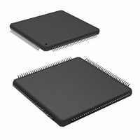
IC ADC 8BIT 500MSPS DUAL 128LQFP
Manufacturer
National Semiconductor
Series
PowerWise®r
Specifications of ADC08D500CIYB/NOPB
Number Of Bits
8
Sampling Rate (per Second)
500M
Data Interface
Serial
Number Of Converters
2
Power Dissipation (max)
1.78W
Voltage Supply Source
Single Supply
Operating Temperature
-40°C ~ 85°C
Mounting Type
Surface Mount
Package / Case
128-LQFP Exposed Pad
Lead Free Status / RoHS Status
Lead free / RoHS Compliant
Other names
*ADC08D500CIYB
*ADC08D500CIYB/NOPB
ADC08D500CIYB
*ADC08D500CIYB/NOPB
ADC08D500CIYB
Available stocks
Company
Part Number
Manufacturer
Quantity
Price
Company:

Part Number:
ADC08D500CIYB/NOPB
Manufacturer:
Texas Instruments
Quantity:
10 000


www.national.com
DIGITAL CONTROL PIN CHARACTERISTICS
V
V
C
DIGITAL OUTPUT CHARACTERISTICS
V
∆ V
V
V
∆ V
I
Z
V
V
POWER SUPPLY CHARACTERISTICS
I
I
P
PSRR1
PSRR2
AC ELECTRICAL CHARACTERISTICS
f
f
f
t
t
OS
A
DR
CLK1
CLK2
CLK2
CL
CH
Symbol
Converter Electrical Characteristics
IH
IL
OD
OS
OS
O
OH
OL
D
IN
The following specifications apply after calibration for V
870mV
Floating, Non-Extended Control Mode, SDR Mode, R
tial. Boldface limits apply for T
O DIFF
OS
P-P
, C
Logic High Input Voltage
Logic Low Input Voltage
Input Capacitance (Notes 11, 13)
LVDS Differential Output Voltage
Change in LVDS Output Swing
Between Logic Levels
Output Offset Voltage, see Figure
1
Output Offset Voltage, see Figure
1
Output Offset Voltage Change
Between Logic Levels
Output Short Circuit Current
Differential Output Impedance
Cal_Run H level output
Cal_Run L level output
Analog Supply Current
Output Driver Supply Current
Power Consumption
D.C. Power Supply Rejection Ratio
A.C. Power Supply Rejection Ratio
Maximum Input Clock Frequency
Minimum Input Clock Frequency
Minimum Input Clock Frequency
Input Clock Duty Cycle
Input Clock Duty Cycle
Input Clock Low Time
Input Clock High Time
L
= 10 pF, Differential, a.c. coupled Sinewave Input Clock, f
Parameter
A
= T
MIN
to T
MAX
(Note 12)
(Note 12)
Each input to ground
Measured differentially, OutV = V
V
Measured differentially, OutV =
GND, V
V
V
Output+ & Output- connected to
0.8V
I
I
PD = PDQ = Low
PD = Low, PDQ = High
PD = PDQ = High
PD = PDQ = Low
PD = Low, PDQ = High
PD = PDQ = High
PD = PDQ = Low
PD = Low, PDQ = High
PD = PDQ = High
Change in Full Scale Error with
change in V
248 MHz, 50mV
Normal Mode (non DES) or DES
Mode
Normal Mode (non DES)
DES Mode
200 MHz ≤ Input clock frequency ≤
800 MHz (Normal Mode)(Note 12)
450 MHz ≤ Input clock frequency ≤
800 MHz (DES Mode)(Note 12)
(Note 12)
(Note 12)
OH
OH
BG
BG
BG
. All other limits T
= -400uA (Note 12)
= 400uA (Note 12)
= Floating, (Note 15)
= Floating
= V
EXT
A
BG
A
= V
= 3300Ω
(Note 15)
= Floating, (Note 15)
A
DR
Conditions
(Continued)
10
from 1.8V to 2.0V
= +1.9V
P-P
±
A
riding on V
0.1%, Analog Signal Source Impedance = 100Ω Differen-
= 25˚C, unless otherwise noted. (Notes 6, 7)
DC
CLK
, OutV = 1.9V, V
= 500 MHz at 0.5V
A
A
,
(Note 8)
Typical
0.012
1200
1.65
0.15
710
510
800
100
561
340
200
112
800
200
450
500
500
IN
1.2
1.8
1.4
0.8
3.5
±
±
−4
30
51
50
50
1
1
FSR (a.c. coupled) = differential
P-P
with 50% duty cycle, V
0.85 x V
0.15 x V
(Note 8)
Limits
1.78
400
920
280
720
665
408
275
157
500
400
400
1.5
0.3
1.0
20
80
20
80
A
A
mV
mV
mV
mV
MHz (min)
mA (max)
mA (max)
mA (max)
W (max)
% (max)
% (max)
(Limits)
ps (min)
ps (min)
V (max)
% (min)
% (min)
V (min)
P-P
P-P
Ohms
Units
P-P
P-P
MHz
MHz
mW
mV
mV
mV
mV
mA
mA
mA
mA
pF
dB
dB
W
V
V
(max)
(max)
(min)
(min)
BG
=
Related parts for ADC08D500CIYB/NOPB
Image
Part Number
Description
Manufacturer
Datasheet
Request
R

Part Number:
Description:
National Semiconductor [8-Bit D/A Converter]
Manufacturer:
National Semiconductor
Datasheet:
Part Number:
Description:
National Semiconductor [Media Coprocessor]
Manufacturer:
National Semiconductor
Datasheet:
Part Number:
Description:
Digitally Controlled Tone and Volume Circuit with Stereo Audio Power Amplifier, Microphone Preamp Stage and National 3D Sound
Manufacturer:
National Semiconductor
Datasheet:
Part Number:
Description:
Digitally Controlled Tone and Volume Circuit with Stereo Audio Power Amplifier, Microphone Preamp Stage and National 3D Sound
Manufacturer:
National Semiconductor
Datasheet:
Part Number:
Description:
AC97 Rev 2 Codec with Sample Rate Conversion and National 3D Sound
Manufacturer:
National Semiconductor
Part Number:
Description:
Manufacturer:
National Semiconductor
Datasheet:
Part Number:
Description:
Manufacturer:
National Semiconductor
Datasheet:
Part Number:
Description:
General Purpose, Low Voltage, Low Power, Rail-to-Rail Output Operational Amplifiers
Manufacturer:
National Semiconductor
Datasheet:
Part Number:
Description:
8-bit 20 MSPS flash A/D converter.
Manufacturer:
National Semiconductor
Datasheet:
Part Number:
Description:
Low Noise Quad Operational Amplifier
Manufacturer:
National Semiconductor
Datasheet:
Part Number:
Description:
Quad Differential Line Receivers
Manufacturer:
National Semiconductor
Datasheet:
Part Number:
Description:
Quad High Speed Trapezoidal? Bus Transceiver
Manufacturer:
National Semiconductor
Datasheet:
Part Number:
Description:
Dual Line Receiver
Manufacturer:
National Semiconductor
Datasheet:
Part Number:
Description:
TTL to 10k ECL Level Translator with Latch
Manufacturer:
National Semiconductor
Datasheet: