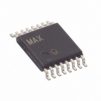
MX7705EUE+ Maxim Integrated Products, MX7705EUE+ Datasheet - Page 17

MX7705EUE+
Manufacturer Part Number
MX7705EUE+
Description
IC ADC 16BIT 2CH 16-TSSOP
Manufacturer
Maxim Integrated Products
Datasheet
1.MX7705EPE.pdf
(33 pages)
Specifications of MX7705EUE+
Number Of Bits
16
Sampling Rate (per Second)
500
Data Interface
MICROWIRE™, QSPI™, Serial, SPI™
Number Of Converters
1
Power Dissipation (max)
755mW
Voltage Supply Source
Single Supply
Operating Temperature
-40°C ~ 85°C
Mounting Type
Surface Mount
Package / Case
16-TSSOP
Lead Free Status / RoHS Status
Lead free / RoHS Compliant
The MX7705 low-power, 2-channel, serial-output ADC
uses a sigma-delta modulator with a digital filter to
achieve 16-bit resolution with no missing codes. The
device includes a PGA, an on-chip input buffer, and a
bidirectional communications port. The MX7705 oper-
ates with a single 2.7V to 5.25V supply.
Fully differential inputs, an internal input buffer, and an
on-chip PGA (gain = 1 to 128) allow low-level signals to
be directly measured, minimizing the requirements for
external signal conditioning. Self-calibration corrects for
gain and offset errors. A programmable digital filter
allows for the selection of the output data rate and first-
notch frequency from 20Hz to 500Hz.
The bidirectional serial SPI-/QSPI-/MICROWIRE-compati-
ble interface consists of four digital control lines (SCLK,
CS, DOUT, and DIN) and provides an easy interface to
microcontrollers (µCs). Connect CS to GND to configure
the MX7705 for 3-wire operation.
AIN1+
AIN2+
AIN1-
AIN2-
REF+
REF-
______________________________________________________________________________________
Detailed Description
SWITCHING
NETWORK
BUFFERED MODE AND CLOSED
S1 AND S2 ARE OPEN IN
IN UNBUFFERED MODE
BUFFER
BUFFER
S1
S2
16-Bit, Low-Power, 2-Channel,
MX7705
PGA
The MX7705 accepts four analog inputs (AIN1+, AIN1-,
AIN2+, and AIN2-) in buffered or unbuffered mode.
Use Table 8 to select the positive and negative input
pair for a fully differential channel. The input buffer iso-
lates the inputs from the capacitive load presented by
the PGA/modulator, allowing for high source-imped-
ance analog transducers. The value of the BUF bit in
the setup register (see the Setup Register section) deter-
mines whether the input buffer is enabled or disabled.
Internal protection diodes, which clamp the analog
input to V
(GND - 0.3V) to (V
device. If the analog input exceeds 300mV beyond the
supplies, limit the input current to 10mA.
When the analog input buffer is disabled, the analog
input drives a typical 7pF (gain = 1) capacitor, C
in series with the 7kΩ typical on-resistance of the track
and hold (T/H) switch (Figure 1). C
of the sampling capacitor, C
itance, C
to (AIN+ - AIN-). The gain determines the value of
C
SIGMA-DELTA
MODULATOR
2ND-ORDER
SAMP
DIVIDER
(Table 5).
STRAY
DD
SERIAL INTERFACE,
REGISTERS,
CONTROL
and/or GND, allow the input to swing from
Sigma-Delta ADC
AND
. During the conversion, C
DIGITAL
FILTER
GENERATOR
CLOCK
DD
+ 0.3V), without damaging the
Functional Diagram
SAMP
CLKIN
CLKOUT
V
GND
CS
SCLK
DIN
DOUT
DRDY
RESET
DD
, and the stray capac-
TOTAL
Analog Inputs
Input Buffers
SAMP
is comprised
charges
TOTAL
17
,


