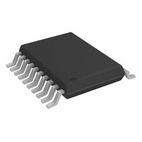
AD7927BRUZ Analog Devices Inc, AD7927BRUZ Datasheet - Page 10

AD7927BRUZ
Manufacturer Part Number
AD7927BRUZ
Description
IC ADC 12BIT 8CH 200KSPS 20TSSOP
Manufacturer
Analog Devices Inc
Specifications of AD7927BRUZ
Data Interface
DSP, MICROWIRE™, QSPI™, Serial, SPI™
Number Of Bits
12
Sampling Rate (per Second)
200k
Number Of Converters
1
Power Dissipation (max)
7.5mW
Voltage Supply Source
Single Supply
Operating Temperature
-40°C ~ 85°C
Mounting Type
Surface Mount
Package / Case
20-TSSOP (0.173", 4.40mm Width)
Resolution (bits)
12bit
Sampling Rate
200kSPS
Input Channel Type
Single Ended
Supply Voltage Range - Analog
2.7V To 5.25V
Supply Current
1.5mA
Number Of Elements
1
Resolution
12Bit
Architecture
SAR
Sample Rate
200KSPS
Input Polarity
Unipolar
Input Type
Voltage
Rated Input Volt
2.5/5V
Differential Input
No
Power Supply Requirement
Analog and Digital
Single Supply Voltage (typ)
3/5V
Single Supply Voltage (min)
2.7V
Single Supply Voltage (max)
5.25V
Dual Supply Voltage (typ)
Not RequiredV
Dual Supply Voltage (min)
Not RequiredV
Dual Supply Voltage (max)
Not RequiredV
Power Dissipation
7.5mW
Differential Linearity Error
-0.9LSB/1.5LSB
Integral Nonlinearity Error
±1LSB
Operating Temp Range
-40C to 85C
Operating Temperature Classification
Industrial
Mounting
Surface Mount
Pin Count
20
Package Type
TSSOP
Input Signal Type
Single-Ended
Lead Free Status / RoHS Status
Lead free / RoHS Compliant
For Use With
EVAL-AD7927CBZ - BOARD EVALUATION FOR AD7927
Lead Free Status / Rohs Status
Compliant
Available stocks
Company
Part Number
Manufacturer
Quantity
Price
Company:
Part Number:
AD7927BRUZ
Manufacturer:
ADI
Quantity:
1 000
Part Number:
AD7927BRUZ
Manufacturer:
ADI/亚德诺
Quantity:
20 000
Company:
Part Number:
AD7927BRUZ-REEL7
Manufacturer:
ADI
Quantity:
3
Company:
Part Number:
AD7927BRUZ-REEL7
Manufacturer:
ADI
Quantity:
1 000
ADD2
0
0
0
0
1
1
1
1
AD7927
PM1 PM0 Mode
1
1
0
0
SEQUENCER OPERATION
The configuration of the SEQ and SHADOW bits in the
Control Register allows the user to select a particular mode of
operation of the sequencer function. Table IV outlines the four
modes of operation of the sequencer.
SEQ SHADOW Sequence Type
0
0
1
1
1
0
1
0
0
1
0
1
ADD1
0
0
1
1
0
0
1
1
Normal Operation. In this mode, the AD7927 remains in full power mode, regardless of the status of any of the logic
inputs. This mode allows the fastest possible throughput rate from the AD7927.
Full Shutdown. In this mode, the AD7927 is in full shutdown mode with all circuitry on the AD7927 powering down.
The AD7927 retains the information in the Control Register while in full shutdown. The part remains in full shutdown
until these bits are changed.
Auto Shutdown. In this mode, the AD7927 automatically enters full shutdown mode at the end of each conversion
when the Control Register is updated. Wake-up time from full shutdown is 1 ms and the user should ensure that 1 ms
has elapsed before attempting to perform a valid conversion on the part in this mode.
Invalid Selection. This configuration is not allowed.
Table II. Channel Selection
This configuration means that the sequence function is not used. The analog input channel selected for each
individual conversion is determined by the contents of the channel address bits ADD0 through ADD2 in each
prior write operation. This mode of operation reflects the traditional operation of a multichannel ADC, without
the sequencer function being used, where each write to the AD7927 selects the next channel for conversion. (See
Figure 2.)
This configuration selects the Shadow Register for programming. The following write operation will load the
contents of the Shadow Register. This will program the sequence of channels to be converted on continuously with
each successive valid CS falling edge. (See Shadow Register, Table V, and Figure 3.) The channels selected need
not be consecutive.
If the SEQ and SHADOW bits are set in this way, the sequence function will not be interrupted upon completion
of the WRITE operation. This allows other bits in the Control Register to be altered between conversions while
in a sequence, without terminating the cycle.
This configuration is used in conjunction with the channel address bits ADD2 to ADD0 to program continuous
conversions on a consecutive sequence of channels from Channel 0 to a selected final channel as determined by the
channel address bits in the Control Register. (See Figure 4.)
ADD0
0
1
0
1
0
1
0
1
Analog Input Channel
V
V
V
V
V
V
V
V
IN
IN
IN
IN
IN
IN
IN
IN
0
1
2
3
4
5
6
7
Table III. Power Mode Selection
Table IV. Sequence Selection
–10–
REV. 0


