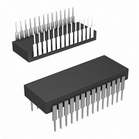
HI1-574ASD-2 Intersil, HI1-574ASD-2 Datasheet

HI1-574ASD-2
Specifications of HI1-574ASD-2
Available stocks
Related parts for HI1-574ASD-2
HI1-574ASD-2 Summary of contents
Page 1
... CAUTION: These devices are sensitive to electrostatic discharge; follow proper IC Handling Procedures. 1-888-INTERSIL or 1-888-468-3774 All other trademarks mentioned are the property of their respective owners. HI-574A, HI-674A FN3096.6 Input) O MSB DIGITAL DATA OUTPUTS LSB | Intersil (and design registered trademark of Intersil Americas Inc. Copyright Intersil Americas Inc. 2001, 2008. All Rights Reserved ...
Page 2
... PART MARKING HI3-574AJN-5 HI3-574AJN-5 HI3-574AJN-5Z (Notes 1, 3) HI3-574AJN-5Z HI3-574AKN-5 HI3-574AKN-5 HI3-574AKN-5Z (Notes 1, 3) HI3-574AKN-5Z HI1-574AJD-5 (Note 2) HI1-574AJD -5 HI1-574AKD-5 (Note 2) HI1-574AKD -5 HI1-574ASD-2 (Note 2) HI1-574ASD -2 HI1-574ATD-2 (Note 2) HI1- 574ATD-2 HI3-674AJN-5 HI3-674AJN-5 HI3-674AJN-5Z (Notes 1, 3) HI3-674AJN-5Z HI3-674AKN-5 HI3-674AKN-5 HI3-674AKN-5Z (Notes 1, 3) HI3-674AKN-5Z HI1-674AKD-5 (Note 2) ...
Page 3
Functional Block Diagram 12/8 CS CONTROL A O LOGIC R/C CE OSCILLATOR DIGITAL CHIP ANALOG CHIP V IN REF V OUT REF +10V REF ANALOG COMMON NOTE: “Nibble” 4-bit digital word. 3 HI-574A, HI-674A BIT OUTPUTS MSB NIBBLE ...
Page 4
... REFOUT . . . . .Indefinite Short To Common, Momentary Short To V Operating Conditions Temperature Range HI3-574Axx-5, HI1-674Axx 0°C to +75°C HI1-574AxD-2, HI1-674AxD .-55°C to +125°C CAUTION: Do not operate at or near the maximum ratings listed for extended periods of time. Exposure to such conditions may adversely impact product reliability and result in failures not covered by warranty ...
Page 5
DC and Transfer Accuracy Specifications PARAMETER Temperature Coefficients Guaranteed Max Change MIN MAX Unipolar Offset Bipolar Offset Full Scale Calibration Power Supply Rejection Max Change In Full Scale Calibration +13.5V < V < +16.5V or +11.4V < ...
Page 6
DC and Transfer Accuracy Specifications PARAMETER DYNAMIC CHARACTERISTICS Resolution (Max) Linearity Error +25°C -55°C to +125°C (Max) Max Resolution For Which No Missing Codes Is Guaranteed +25° MIN MAX Unipolar Offset (Max) Adjustable to Zero Bipolar ...
Page 7
DC and Transfer Accuracy Specifications PARAMETER Operating Current I LOGIC I +15V Supply CC I -15V Supply EE Power Dissipation ±15V, +5V ±12V, +5V Internal Reference Voltage MIN MAX Output current, available for external loads (external load ...
Page 8
Timing Specifications (HI-574A) +25°C, Note 5, Unless Otherwise Specified. (Continued) SYMBOL READ MODE t Access Time from Data Valid After CE Low HD t Output Float Delay Setup SSR t R/C to ...
Page 9
Pin Descriptions PIN SYMBOL DESCRIPTION 1 V Logic supply pin (+5V) LOGIC 2 12/8 Data Mode Select - Selects between 12-bit and 8-bit output modes Chip Select - Chip Select high disables the device Byte Address/Short ...
Page 10
Temperature Coefficients The temperature coefficients for full-scale calibration, unipolar offset, and bipolar offset specify the maximum change from the initial (25°C) value to the value MAX Power Supply Rejection The standard specifications for the HI-X74A assume ...
Page 11
... Sample/Holds are compatible with the HI-574A in the manner described above. These will require an additional wideband buffer amplifier to lower their output impedance. A simpler solution is to use the Intersil HA-5320 Sample/Hold, which was designed for use with the HI-574A ...
Page 12
Connect the Analog signal to pin 13 for a ±5V range pin 14 for a ±10V range. Calibration of offset and gain is ...
Page 13
Conversion Start A conversion may be initiated as shown in Table logic transition on any of three inputs: CE R/C. The last of the three to reach the correct state starts the conversion, so one, ...
Page 14
INPUT BUFFERS 12 R/C CE EOC9 LATCH O EOC13 14 HI-574A, HI-674A A ADDRESS BUS STS 2 27 12/8 DB11 (MSB ...
Page 15
HI-574A, HI-674A t HRL R STS t HDR DATA DB11-DB0 VALID FIGURE 7. LOW PULSE FOR R/C - OUTPUTS ENABLED AFTER CONVERSION R/C t HRH STS t HDR t DDR HIGH-Z DB11-DB0 DATA VALID FIGURE 8. HIGH PULSE ...
Page 16
Die Characteristics DIE DIMENSIONS: Analog: 3070mm x 4610mm Digital: 1900mm x 4510mm METALLIZATION: Digital Type: Nitrox ±2k Å Å Thickness: 10k Metal 1: AlSiCu ±1k Å Å Thickness: 8k Metal 2: AlSiCu ±2k Å Å Thickness: 16k Analog Type: Al ...
Page 17
Ceramic Dual-In-Line Metal Seal Packages (SBDIP) -A- -D- E -B- bbb BASE S2 PLANE -C- SEATING PLANE ccc ...
Page 18
... Accordingly, the reader is cautioned to verify that data sheets are current before placing orders. Information furnished by Intersil is believed to be accurate and reliable. However, no responsibility is assumed by Intersil or its subsidiaries for its use; nor for any infringements of patents or other rights of third parties which may result from its use ...


