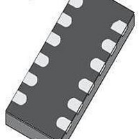
STMPE321QTR STMicroelectronics, STMPE321QTR Datasheet - Page 10

STMPE321QTR
Manufacturer Part Number
STMPE321QTR
Description
IC CTLR TOUCH KEY 3CH 12-QFN
Manufacturer
STMicroelectronics
Series
S-Touch™r
Type
Capacitiver
Specifications of STMPE321QTR
Number Of Inputs/keys
3 Key
Resolution (bits)
8 b
Data Interface
I²C
Data Rate/sampling Rate (sps, Bps)
100k
Voltage - Supply
1.65 V ~ 1.95 V
Mounting Type
Surface Mount
Package / Case
12-QFN
Voltage Supply Source
Single Supply
Resolution
7 bit to 10 bit
Interface Type
I2C
Supply Voltage (max)
1.95 V
Supply Voltage (min)
1.65 V
Mounting Style
SMD/SMT
Lead Free Status / RoHS Status
Lead free / RoHS Compliant
Operating Temperature
-
Sampling Rate (per Second)
-
Lead Free Status / Rohs Status
Details
Other names
497-8985-2
Available stocks
Company
Part Number
Manufacturer
Quantity
Price
Company:
Part Number:
STMPE321QTR
Manufacturer:
MICREL
Quantity:
54
I2C interface
3
10/40
I
The following features are supported by the I
●
●
●
●
●
●
●
Start condition
A Start condition is identified by a falling edge of SDATA while SCLK is stable at high state.
A Start condition must precede any data/command transfer. The device continuously
monitors for a Start condition and does not respond to any transaction unless one is
encountered.
Stop condition
A Stop condition is identified by a rising edge of SDATA while SCLK is stable at high state.
A Stop condition terminates communication between the slave device and bus master. A
read command that is followed by NoAck can be followed by a Stop condition to force the
slave device into idle mode. When the slave device is in idle mode, it is ready to receive the
next I
operation to the registers.
Acknowledge bit (ACK)
The acknowledge bit is used to indicate a successful byte transfer. The bus transmitter
releases the SDATA after sending eight bits of data. During the ninth bit, the receiver pulls
the SDATA low to acknowledge the receipt of the eight bits of data. The receiver may leave
the SDATA in high state if it does not acknowledge the receipt of the data.
Data Input
The device samples the data input on SDATA on the rising edge of the SCLK. The SDATA
signal must be stable during the rising edge of SCLK and the SDATA signal must change
only when SCLK is driven low.
Memory addressing
For the bus master to communicate to the slave device, the bus master must initiate a Start
condition, followed by the slave device address. Accompanying the slave device address,
there is a Read/WRITE bit (R/W). The bit is set to 1 for a read operation, and 0 for a write
operation.
If a match occurs on the slave device address, the corresponding device gives an
acknowledgement on the SDA during the 9th bit time. If there is no match, it deselects itself
from the bus by not responding to the transaction.
2
C interface
I
Compliance with Philips I
Standard (up to 100 kbps) and fast (up to 400 kbps) modes.
7-bit and 10-bit device addressing modes
General call
Start/Restart/Stop
I
2
2
2
C slave device
C address is 0x58 (0xB0/0xB1 for write/read, including the LSB)
C transaction. A Stop condition at the end of a write command stops the write
2
Doc ID 15791 Rev 3
C specification version 2.1
2
C interface:
STMPE321


