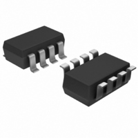
MAX5474EKA+T Maxim Integrated Products, MAX5474EKA+T Datasheet - Page 7

MAX5474EKA+T
Manufacturer Part Number
MAX5474EKA+T
Description
IC POT DGTL 32-TAP NV SOT23-8
Manufacturer
Maxim Integrated Products
Datasheet
1.MAX5471EZTT.pdf
(12 pages)
Specifications of MAX5474EKA+T
Taps
32
Resistance (ohms)
50K
Number Of Circuits
1
Temperature Coefficient
35 ppm/°C Typical
Memory Type
Non-Volatile
Interface
Up/Down
Voltage - Supply
2.7 V ~ 5.25 V
Operating Temperature
-40°C ~ 85°C
Mounting Type
Surface Mount
Package / Case
SOT-23-8
Resistance In Ohms
50K
Number Of Pots
Single
Taps Per Pot
32
Resistance
50 KOhms
Wiper Memory
Non Volatile
Digital Interface
Serial (3-Wire)
Operating Supply Voltage
5 V
Supply Current
0.4 mA
Maximum Operating Temperature
+ 85 C
Minimum Operating Temperature
- 40 C
Description/function
32-Step Nonvolatile Up/Down 50Kohm Potentiometer
Mounting Style
SMD/SMT
Supply Voltage (max)
5.25 V
Supply Voltage (min)
2.7 V
Lead Free Status / RoHS Status
Lead free / RoHS Compliant
Other names
MAX5474EKA+T
Figure 1. Digital Interface and Timing Diagram
The MAX5471/MAX5472/MAX5474/MAX5475 contain a
resistor array with 31 resistive elements (Figures 2 and
3). The MAX5471/MAX5474 have a total end-to-end
resistance of 50kΩ, and the MAX5472/MAX5475 have
an end-to-end resistance of 100kΩ. The MAX5471/
MAX5472 wiper is connected to the high terminal, and
the low terminal is internally connected to ground, mak-
ing the device a variable resistor. The MAX5474/
MAX5475 allow access to the high, low, and wiper ter-
minals for a standard voltage-divider configuration.
The wiper is moved among the 32 tap points through a
simple 3-wire interface. Nonvolatile memory allows the
wiper position to be stored and recalled to the same
point upon power-up.
Logic inputs CS, U/D, and INC control the wiper posi-
tion and store it in nonvolatile memory (see the Truth
Table). The chip-select (CS) input enables the serial
interface when low and disables the interface when
high. The position of the wiper is stored when CS transi-
tions from low to high and INC is high (see the Storing
Wiper Position section).
With the serial interface active (CS low), a high-to-low
(falling edge) transition on INC moves the wiper posi-
tion by one resistive element in the direction deter-
mined by the state of U/D. If U/D is high, the wiper
increments and it increases the resistance between W
and L (it decreases the resistance between H and W).
If U/D is low, the wiper decrements and it decreases
the resistance between W and L (it increases the resis-
tance between H and W). The direction of the wiper
INC
U/D
V
CS
W
NOTE: V
W
IS NOT A DIGITAL SIGNAL. IT REPRESENTS A WIPER TRANSITION.
t
_______________________________________________________________________________________
CI
32-Tap, Nonvolatile, Linear-Taper Digital
Detailed Description
t
IW
t
IL
t
CYC
t
ID
Digital Interface
t
IH
t
DI
Potentiometers in SOT23
t
IC
(state of U/D) can be changed at any time as long as
the setup and hold times are met.
Since the MAX5471/MAX5472 have the wiper internally
connected to H, an increment command increases the
resistance between H and GND, and a decrement com-
mand decreases the resistance between H and GND.
The wiper performs a make-before-break transition,
ensuring that there is never an open circuit during a
transition from one resistor tap to another. When the
wiper is at either end of the resistor array (max/min),
additional transitions in the direction of the endpoint do
not change the counter value (the wiper does not wrap
around).
The position of the wiper is stored in nonvolatile memo-
ry whenever CS transitions low-to-high (rising edge)
while INC is high. Upon power-up, the wiper returns to
this stored position. By keeping INC low while taking
CS high, the serial interface can be disabled and the
potentiometer placed in standby without storing the lat-
est wiper position. The factory-default wiper position
is midscale.
These devices can also be operated like a one-time
programmable (OTP) device. Once the desired wiper
position is trimmed and stored in nonvolatile memory,
disable the serial interface by connecting CS to V
and INC to GND. The disabled interface places the
device in standby and disallows any changes to the
wiper position. In OTP mode, these devices become a
fixed 3-terminal potentiometer or a 1-terminal resistor to
GND with less than 1µA of supply current.
t
CPH
WIPER POSITION
STORED
t
WSC
WIPER POSITION
NOT STORED
Storing Wiper Position
t
IK
DD
7
,


