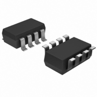
MAX5474EKA+T Maxim Integrated Products, MAX5474EKA+T Datasheet - Page 8

MAX5474EKA+T
Manufacturer Part Number
MAX5474EKA+T
Description
IC POT DGTL 32-TAP NV SOT23-8
Manufacturer
Maxim Integrated Products
Datasheet
1.MAX5471EZTT.pdf
(12 pages)
Specifications of MAX5474EKA+T
Taps
32
Resistance (ohms)
50K
Number Of Circuits
1
Temperature Coefficient
35 ppm/°C Typical
Memory Type
Non-Volatile
Interface
Up/Down
Voltage - Supply
2.7 V ~ 5.25 V
Operating Temperature
-40°C ~ 85°C
Mounting Type
Surface Mount
Package / Case
SOT-23-8
Resistance In Ohms
50K
Number Of Pots
Single
Taps Per Pot
32
Resistance
50 KOhms
Wiper Memory
Non Volatile
Digital Interface
Serial (3-Wire)
Operating Supply Voltage
5 V
Supply Current
0.4 mA
Maximum Operating Temperature
+ 85 C
Minimum Operating Temperature
- 40 C
Description/function
32-Step Nonvolatile Up/Down 50Kohm Potentiometer
Mounting Style
SMD/SMT
Supply Voltage (max)
5.25 V
Supply Voltage (min)
2.7 V
Lead Free Status / RoHS Status
Lead free / RoHS Compliant
Other names
MAX5474EKA+T
The MAX5471/MAX5472/MAX5474/MAX5475 are
always in standby mode, except during the transition of
a logic input or while the wiper position is being stored.
When in standby mode, the static supply current is
reduced to less than 1µA and the resistive terminals (H,
W, and L) are unaffected.
32-Tap, Nonvolatile, Linear-Taper Digital
Potentiometers in SOT23
↓ = High-to-low transition.
↑ = Low-to-high transition.
X = Don’t care.
Figure 2. MAX5471/MAX5472 Functional Diagram
8
GND
V
U/D
INC
CS
DD
_______________________________________________________________________________________
CS
H
L
L
L
↓
↑
↑
6
2
1
4
3
NONVOLATILE
UP/DOWN
COUNTER
MEMORY
U/D
MAX5471
MAX5472
H
L
X
X
X
X
X
32-POSITION
DECODER
INC
H
↓
↓
↑
X
X
L
R
R
R
R
31
30
2
1
H
5
Position not stored
Standby Mode
Position stored
S
S
S
S
S
S
32
31
30
Decrement
No change
No change
No change
3
2
1
Increment
Truth Table
W
R
W
The MAX5471/MAX5472/MAX5474/MAX5475 are
intended for circuits requiring digitally controlled
adjustable resistance, such as LCD contrast control
(where voltage biasing adjusts the display contrast), or
programmable filters with adjustable gain and/or cutoff
frequency.
Figures 4 and 5 show an application where the voltage-
divider or variable resistor is used to make an
adjustable, positive LCD-bias voltage. The op amp pro-
vides buffering and gain to the resistor-divider network
made by the potentiometer (Figure 4) or to a fixed
resistor and a variable resistor (Figure 5).
Figure 6 shows the configuration of a 1st-order pro-
grammable filter. The gain of the filter is adjusted by
R2, and the cutoff frequency is adjusted by R3. Use the
following equations to calculate the gain (G) and the
3dB cutoff frequency (f
Figure 3. MAX5474/MAX5475 Functional Diagram
GND
V
U/D
INC
CS
DD
2
3
1
5
4
NONVOLATILE
UP/DOWN
COUNTER
MEMORY
MAX5474
MAX5475
Applications Information
f
C
32-POSITION
=
Positive LCD Bias Control
DECODER
G
C
):
2
= +
π
1
×
Programmable Filter
R
1
R
R
R
R
R
31
30
R
3
2
1
1
2
×
H
L
6
8
C
S
S
S
S
S
S
32
31
30
3
2
1
R
W
7
W


