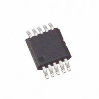
ISL23711UIU10Z Intersil, ISL23711UIU10Z Datasheet - Page 4

ISL23711UIU10Z
Manufacturer Part Number
ISL23711UIU10Z
Description
IC POT DIGITAL CONTROL 10-MSOP
Manufacturer
Intersil
Series
XDCP™r
Datasheet
1.ISL23711WIU10Z-T.pdf
(9 pages)
Specifications of ISL23711UIU10Z
Taps
128
Resistance (ohms)
50K
Number Of Circuits
1
Temperature Coefficient
50 ppm/°C Typical
Memory Type
Volatile
Interface
I²C, 2-Wire Serial
Voltage - Supply
2.7 V ~ 5.5 V
Operating Temperature
-40°C ~ 85°C
Mounting Type
Surface Mount
Package / Case
10-MSOP, Micro10™, 10-uMAX, 10-uSOP
Resistance In Ohms
50K
Lead Free Status / RoHS Status
Lead free / RoHS Compliant
Available stocks
Company
Part Number
Manufacturer
Quantity
Price
Company:
Part Number:
ISL23711UIU10Z
Manufacturer:
INTERSIL
Quantity:
101
Operating Specifications
SERIAL INTERFACE SPECS
Hysteresis
SYMBOL
(Note 13)
(Note 14)
t
t
t
t
t
t
I
SU:STO
HD:STO
SU:STA
HD:STA
SU:DAT
HD:DAT
LkgDig
t
I
t
t
I
Vpor
Cpin
f
t
V
HIGH
V-SB
LOW
DCP
V
CC1
I
V
SCL
t
BUF
I
t
SB
AA
V-
OL
IN
IH
IL
V
Write/Read
V- Supply Current, Volatile Write/Read f
V
V- Current (Standby)
Leakage Current, at Pins SDA, SCL,
A0, and A1
DCP Wiper Response Time
Power-on Recall for V
A0, A1, SDA, and SCL Input Buffer
LOW Voltage
A0, A1, SDA, and SCL Input Buffer
HIGH Voltage
SDA and SCL Input Buffer Hysteresis
SDA Output Buffer LOW Voltage,
Sinking 4mA
A0, A1, SDA, and SCL Pin
Capacitance
SCL Frequency
Pulse Width Suppression Time at SDA
and SCL Inputs
SCL Falling Edge to SDA Output Data
Valid
Time the Bus Must be Free Before the
Start of a New Transmission
Clock LOW Time
Clock HIGH Time
START Condition Setup Time
START Condition Hold Time
Input Data Setup Time
Input Data Hold Time
STOP Condition Setup Time
STOP Condition Setup Time
CC
CC
Supply Current, Volatile
Current (Standby)
PARAMETER
4
Over the recommended operating conditions unless otherwise specified.
CC
f
Read and Write states only)
Read and Write states only)
V
V
V- = -5.5V, I
V- = -2.7V, I
Voltage at pin from GND to V
SCL falling edge of last bit of DCP Data Byte to
wiper change
Any pulse narrower than the max spec is
suppressed
SCL falling edge crossing 30% of V
exits the 30% to 70% of V
SDA crossing 70% of V
condition, to SDA crossing 70% of V
the following START condition
Measured at the 30% of V
Measured at the 70% of V
SCL rising edge to SDA falling edge. Both
crossing 70% of V
From SDA falling edge crossing 30% of V
SCL falling edge crossing 70% of V
From SDA exiting the 30% to 70% of V
window, to SCL rising edge crossing 30% of V
From SCL rising edge crossing 70% of V
SDA entering the 30% to 70% of V
From SCL rising edge crossing 70% of V
SDA rising edge crossing 30% of V
From SDA rising edge to SCL falling edge. Both
crossing 70% of V
SCL
SCL
CC
CC
= +5.5V, I
= +3.6V, I
= 400kHz; SDA = Open; (for I
= 400kHz; SDA = Open; (for I
ISL23711
2
2
C Interface in Standby State
C Interface in Standby State
TEST CONDITIONS
2
2
C Interface in Standby State
C Interface in Standby State
CC
CC
CC
CC
CC
CC
during a STOP
CC
window
crossing
crossing
2
2
CC
CC
CC
CC
C, Active,
C, Active,
CC
, until SDA
window
CC
during
CC
CC
CC
, to
to
to
CC
0.7*V
0.05*
1300
1300
-100
-500
-300
V
MIN
-0.3
600
600
600
100
600
600
-10
CC
0
0
CC
(Note 1)
TYP
2.5
1
0.3*V
V
MAX
200
500
300
400
900
0.3
0.4
CC
10
10
50
-1
-1
CC
+
August 16, 2005
UNIT
FN6127.0
kHz
µA
µA
nA
nA
nA
nA
µA
µs
pF
ns
ns
ns
ns
ns
ns
ns
ns
ns
ns
ns
V
V
V
V
V


