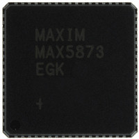
MAX5873EGK+D Maxim Integrated Products, MAX5873EGK+D Datasheet - Page 12

MAX5873EGK+D
Manufacturer Part Number
MAX5873EGK+D
Description
IC DAC 12BIT 200MSPS DUAL 68-QFN
Manufacturer
Maxim Integrated Products
Datasheet
1.MAX5873EGKD.pdf
(16 pages)
Specifications of MAX5873EGK+D
Settling Time
14ns
Number Of Bits
12
Data Interface
Parallel
Number Of Converters
2
Voltage Supply Source
Analog and Digital
Power Dissipation (max)
300mW
Operating Temperature
-40°C ~ 85°C
Mounting Type
Surface Mount
Package / Case
68-QFN Exposed Pad
Conversion Rate
200 MSPs
Resolution
12 bit
Interface Type
Parallel
Supply Voltage (max)
1.89 V, 3.465 V
Supply Voltage (min)
1.71 V, 3.135 V
Maximum Operating Temperature
+ 85 C
Mounting Style
SMD/SMT
Minimum Operating Temperature
- 40 C
Lead Free Status / RoHS Status
Lead free / RoHS Compliant
12-Bit, 200Msps, High-Dynamic-Performance,
Dual DAC with CMOS Inputs
Figure 4. Timing Relationships Between Clock and Input Data for (a) Dual-Port (Parallel) Mode and (b) Single-Port (Interleaved) Mode
The MAX5873 features a flexible differential clock input
(CLKP, CLKN) with a separate supply (AV
achieve optimum jitter performance. Use an ultra-low
jitter clock to achieve the required noise density. Clock
jitter must be less than 0.5ps
fied noise density. For that reason, the CLKP/CLKN
input source must be designed carefully. The differen-
tial clock (CLKN and CLKP) input can be driven from a
single-ended or a differential clock source. Differential
12
______________________________________________________________________________________
DATA
Q OUT
SELIQ
I OUT
DATA11–DATA0, XOR
CLK
IN
Q - 6
DAC OUTPUT
I - 6
Applications Information
CLK
t
S
N - 6
N - 1
I0
RMS
t
PD
t
H
Q - 5
for meeting the speci-
I - 5
CLK Interface
Q0
t
S
N - 5
t
PD
(b) SINGLE-PORT (INTERLEAVED) TIMING DIAGRAM
N
(a) DUAL-PORT (PARALLEL) TIMING DIAGRAM
CLK
I1
) to
t
H
clock drive is required to achieve the best dynamic
performance from the DAC. For single-ended opera-
tion, drive CLKP with a low noise source and bypass
CLKN to GND with a 0.1µF capacitor.
Figure 5 shows a convenient and quick way to apply a
differential signal created from a single-ended source
(e.g., HP/Agilent 8644B signal generator) and a wide-
band transformer. Alternatively, these inputs can be dri-
ven from a CMOS-compatible clock source; however, it is
recommended to use sinewave or AC-coupled differential
ECL/PECL drive for best dynamic performance.
N - 4
Q1
Q - 4
I - 4
N + 1
I2
N - 3
Q2
Q - 3
I - 3
N + 2
I3
N - 2
Q - 2
I - 2
Q3


