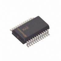
MAX5187BEEG+ Maxim Integrated Products, MAX5187BEEG+ Datasheet - Page 7

MAX5187BEEG+
Manufacturer Part Number
MAX5187BEEG+
Description
IC DAC 8BIT 40MHZ 24-QSOP
Manufacturer
Maxim Integrated Products
Datasheet
1.MAX5190BEEG.pdf
(15 pages)
Specifications of MAX5187BEEG+
Settling Time
25µs
Number Of Bits
8
Data Interface
Parallel
Number Of Converters
1
Voltage Supply Source
Analog and Digital
Operating Temperature
-40°C ~ 85°C
Mounting Type
Surface Mount
Package / Case
24-QSOP
Lead Free Status / RoHS Status
Lead free / RoHS Compliant
Power Dissipation (max)
-
11, 12, 22
14–19
PIN
10
13
20
21
23
24
1
2
3
4
5
6
7
8
9
8-Bit, 40MHz, Current/Voltage-Output DACs
DACEN
D1–D6
NAME
AGND
DGND
OUTN
OUTP
REFO
CREF
AV
DV
REFR
CLK
REN
PD
CS
D0
D7
DD
DD
_______________________________________________________________________________________
Reference Bias Bypass
Positive Analog Output. Current output for MAX5187; voltage output for MAX5190.
Negative Analog Output. Current output for MAX5187; voltage output for MAX5190.
Analog Ground
Analog Positive Supply, +2.7V to +3.3V
DAC Enable, Digital Input
0: Enter DAC standby mode with PD = DGND
1: Power-up DAC with PD = DGND
X: Enter shutdown mode with PD = DV
Power-Down Select
0: Enter DAC standby mode (DACEN = DGND) or power-up DAC (DACEN = DV
1: Enter shutdown mode
Active-Low Chip Select
Clock Input
Active-Low Reference Enable. Connect to DGND to activate on-chip +1.2V reference.
Digital Ground
Data Bit D0 (LSB)
Data Bit D1–D6
Data Bit D7 (MSB)
Digital Supply, +2.7V to +3.3V
Reference Input
Reference Output
DD
(X = don’t care)
FUNCTION
Pin Description
DD
)
7


