66109-2 TE Connectivity, 66109-2 Datasheet - Page 2
66109-2
Manufacturer Part Number
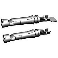
66109-2
Description
Connector Contact,SKT,CRIMP Terminal
Manufacturer
TE Connectivity
Series
Type III+r
Specifications of 66109-2
Insulation Support
Yes
Termination Method To Wire/cable
Crimp
Wire/cable Type
Discrete Wire
Grade
Commercial
High Current
No
Termination End Plating
Bright Tin-Lead
Pin Diameter (mm [in])
1.57 [0.062]
Wire Range (mm [awg])
0.12-0.24² [26-24]
Spring Material
Stainless Steel
Used With
G Series Connectors, M Series Connectors, CPC Connectors
Contact Type
Socket
Contact Classification
Signal
Contact Plating, Mating Area, Material
Bright Tin-Lead
Contact Base Material
Brass
Contact Size
16
Rohs/elv Compliance
Not ELV/RoHS compliant
Lead Free Solder Processes
Not relevant for lead free process
Accepts Wire Insulation Diameter, Range (mm [in])
0.89 – 1.40 [0.035 – 0.055]
Applies To
Wire/Cable
Test Current (a)
13.0
Packaging Method
Loose Piece
Packaging Quantity
1,000 Box/Carton


3.3.
3.4.
3.5.
Exam ination of product.
Term ination resistance, specified
current.
Term ination resistance, dry circuit.
Current cycling.
Contact engaging force.
Contact separating force.
Rev E
Rating
!
!
Perform ance and Test Description
Contacts shall be designed to m eet the electrical, m echanical and environm ental perform ance
requirem ents specified in Figure 1. Unless otherwise specified, all tests shall be perform ed at am bient
environm ental conditions per Test Specification 109-1.
Test Requirem ents and Procedures Sum m ary
Test Description
Current/Voltage: The continuous current rating for individual contacts cannot be applied directly to
the num ber of contacts as they are dependent on the therm al and physical properties of the
m aterial. System design shall assure that continuous current rating does not create internal hot
spots that exceed the tem perature designated by the connector specification, during steady state
or transient conditions.
Operating tem perature:
•
•
-55 to 150°C for precious m etal plated contacts
-55 to 90°C for tin plated contacts
See Figure 4.
Meet requirem ents of product
drawing and Application
Specification 114-10004.
See Figure 4.
Term ination resistance, specified
current.
See Figure 5 for m axim um force
per contact.
See Figure 5 for m inim um force per
contact.
Figure 1 (continued)
MECHANICAL
Requirem ents
ELECTRICAL
TE Spec 109-6-1.
Visual, dim ensional and functional
per applicable inspection plan.
TE Spec 109-25.
Measure potential drop of m ated
contacts after stabilizing.
Calculate resistance.
See Figure 3.
Subject m ated contact pair to 50
m illivolts open circuit at 100
m illiam peres m axim um .
See Figure 3.
TE Spec 109-51, Condition B, Test
Method 3.
Subject m ated contacts to 500
cycles at 125% of specified current
for 30 m inutes ON and 15 m inutes
OFF.
TE Spec 109-35.
Measure force to engage using
gage 2 as indicated in Figure 6.
Engagem ent depth: .230 ± .010.
TE Spec 109-35.
Size 3 tim es using gage 2 as
indicated in Figure 6, insert gage 1
and m easure force to separate.
Separation depth: .230 ± .010.
Procedure
108-10042
2 of 7
Related parts for 66109-2
Image
Part Number
Description
Manufacturer
Datasheet
Request
R

Part Number:
Description:
CONTACT, SOCKET, 26-24AWG, CRIMP
Manufacturer:
TE Connectivity
Datasheet:
Part Number:
Description:
CONTACT, SOCKET, 26-24AWG, CRIMP
Manufacturer:
TE Connectivity
Datasheet:

Part Number:
Description:
III+ SKT,26-24,30AU
Manufacturer:
TE Connectivity
Datasheet:


Part Number:
Description:
High Speed / Modular Connectors 30P HEADER ASSY
Manufacturer:
TE Connectivity
Datasheet:

Part Number:
Description:
High Speed / Modular Connectors REC 6X005P R/A LT B-PLANE HS3
Manufacturer:
TE Connectivity
Datasheet:

Part Number:
Description:
High Speed / Modular Connectors 2MM HM RCPT 50P R/A AU
Manufacturer:
TE Connectivity
Datasheet:

Part Number:
Description:
High Speed / Modular Connectors 2MM HM RCPT 50P R/A AU
Manufacturer:
TE Connectivity
Datasheet:


Part Number:
Description:
Manufacturer:
TE Connectivity
Datasheet:


Part Number:
Description:
Manufacturer:
TE Connectivity
Datasheet:

Part Number:
Description:
Manufacturer:
TE Connectivity
Datasheet:

Part Number:
Description:
Manufacturer:
TE Connectivity
Datasheet: