E2EX3D1N Omron, E2EX3D1N Datasheet - Page 37
E2EX3D1N
Manufacturer Part Number
E2EX3D1N
Description
Manufacturer
Omron
Datasheet
1.E2EX3D1N.pdf
(48 pages)
Specifications of E2EX3D1N
Proximity Sensor Type
Inductive
Output Type
NPN/PNP
Proximity Sensor Sensing Distance
3mm
Proximity Sensor Sensing Distance Range
2 to 7mm
Proximity Sensor Switching Mode
NO
Mounting
Panel
Operating Temp Range
-25C to 70C
Operating Temperature Classification
Commercial
Operating Supply Voltage (min)
10V
Operating Supply Voltage (typ)
12/15/18/24V
Operating Supply Voltage (max)
30V
Pin Count
4
Lead Free Status / Rohs Status
Compliant


Connection to a PLC
Required Conditions
Connection to a PLC is possible if the specifications of the PLC and
the Proximity Sensor satisfy the following conditions. (The meanings
of the symbols are given below.)
1. The ON voltage of the PLC and the residual voltage of the Prox-
2. The OFF current of the PLC and the leakage current of the Prox-
3. The ON current of the PLC and the control output (I
■ Precautions for AC/DC 2-wire Proximity Sensors in Operation
Connection
DC 2-wire
AC 2-wire
imity Sensor must satisfy the following.
V
imity Sensor must satisfy the following.
I
(If the OFF current is not listed in the specifications, take it to be
1.3 mA.)
Proximity Sensor must satisfy the following.
I
The ON current of the PLC will vary, however, with the power sup-
ply voltage and the input impedance used as shown in the follow-
ing equation.
I
Model
OFF ≥
OUT(min)
ON
ON
= (V
≤ V
I
leak
CC
CC
≤ I
ON
– V
– V
AND (serial connection)
OR
(parallel connection)
AND (serial connection)
≤ I
R
R
Connection type
–
OUT(max)
V
PC
)/R
IN
OUT
Correct
Correct
) of the
Incorrect
Correct
Method
Load
Load
Load
Load
Load
E2E/E2E2
Example
In this example, the above conditions are checked for when the PLC
model is the C200H-ID212, the Proximity Sensor model is the E2E-
X7D1-N, and the power supply voltage is 24 V.
1. V
2. I
3. I
V
I
I
R
V
I
I
V
Values in parentheses are for the following PLC model and Proximity
Sensor model.
PLC: C200H-ID212
Proximity Sensor: E2E-X7D1-N
V
V s × 100 V
ON
OFF
leak
OUT
ON
R
CC
IN
PC
: Output residual voltage of Proximity Sensor (3 V)
: ON current of PLC (typ. 7 mA)
: Input impedance of PLC (3 k Ω )
≈ 4.5 mA
Therefore,
I
: Leakage current of Proximity Sensor (0.8 mA)
: OFF current of PLC (1.3 mA)
: Internal residual voltage of PLC (4 V)
: Power supply voltage (PLC: 20.4 to 26.4 V)
: ON voltage of PLC (14.4 V)
: Control output of Proximity Sensor (3 to 100 mA)
OFF
ON
OUT(min)
ON
= [V
(1.3 mA) ≥ I
(14.4 V) ≤ V
CC
(3 mA) ≤ I
(20.4 V) – V
The Sensors connected together must satisfy the
following conditions.
V
N: No. of Sensors
V
V
If each Proximity Sensor is not supplied with the
rated voltage and current, the indicator will not be lit
properly or unnecessary pulses may be output for
approximately 1 ms.
The Sensors connected together must satisfy the
following conditions.
N x i ≤ Load reset current
N: No. of Sensors
i: Leakage current of each Sensor
If the MY Relay, which operates at 24 VDC, is used
as a load for example, a maximum of four Proximity
Sensors can be connected to the load.
If 100 or 200 VAC is imposed on the Proximity
Sensors, V
will be obtained from the following.
V
Sensors) (V)
Therefore, if V
voltage, the load will not operate.
A maximum of three Proximity Sensors can be
connected in series provided that the supply voltage
is 100 V minimum.
S
R
S
L
: Residual voltage of each Sensor
: Supply voltage
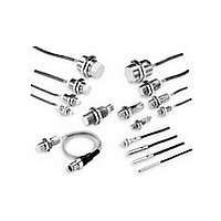
Cylindrical Proximity Sensor
= V
– N x V
leak
CC
ON
S
(20.4 V) – V
(0.8 mA): OK
(4.5 mA): OK
– (residual voltage x No. of Proximity
R
R
L
(3 V) –
≥ Load operating voltage
(i.e., the voltage imposed on the load)
L
is lower than the load operating
R
V
Description
(3 V) = 17.4 V: OK
PC
(4 V)]/R
IN
(3 k Ω )
37
Related parts for E2EX3D1N
Image
Part Number
Description
Manufacturer
Datasheet
Request
R

Part Number:
Description:
Proximity Sensors E2E-X5ME1 W/5M CABLE
Manufacturer:
Omron
Datasheet:
Part Number:
Description:
Proximity Sensors Prox Plug In
Manufacturer:
Omron
Datasheet:
Part Number:
Description:
Proximity Sensors PROX E2E-C1C1 W/ 5 M ETER CABLE
Manufacturer:
Omron
Datasheet:
Part Number:
Description:
Proximity Sensors E2E-X1C1 W/ SPECIAL ATTRIBUTES
Manufacturer:
Omron
Datasheet:
Part Number:
Description:
Proximity Sensors PROX E2E-CR8C1 ROBOT CABLE 2M
Manufacturer:
Omron
Datasheet:
Part Number:
Description:
Proximity Sensors E2E-X1B1 W/ 2M ROBOT IC CABLE
Manufacturer:
Omron
Datasheet:
Part Number:
Description:
Proximity Sensors Proximity Sensor
Manufacturer:
Omron
Datasheet:
Part Number:
Description:
Proximity Sensors PROXIMITY SENSOR
Manufacturer:
Omron
Datasheet:
Part Number:
Description:
Proximity Sensors Prox M18 7Mm Nc
Manufacturer:
Omron
Datasheet:
Part Number:
Description:
Proximity Sensors PROX
Manufacturer:
Omron
Datasheet:

Part Number:
Description:
PROXIMITY SENSOR
Manufacturer:
Omron
Datasheet:
