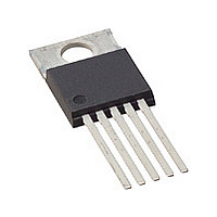
FSCM0565RCYDTU_NL Fairchild Semiconductor, FSCM0565RCYDTU_NL Datasheet - Page 12

FSCM0565RCYDTU_NL
Manufacturer Part Number
FSCM0565RCYDTU_NL
Description
Manufacturer
Fairchild Semiconductor
Datasheet
1.FSCM0565RCYDTU_NL.pdf
(20 pages)
Specifications of FSCM0565RCYDTU_NL
Power Switch Family
FSCM0565R
Power Switch On Resistance
1.76Ohm
Output Current
2.5A
Number Of Outputs
Single
Mounting
Through Hole
Supply Current
2.5mA
Package Type
TO-220
Operating Temperature (min)
-25C
Operating Temperature (max)
85C
Operating Temperature Classification
Commercial
Pin Count
5 +Tab
Power Dissipation
120W
Lead Free Status / Rohs Status
Compliant
control IC are built in one package. This makes it easy for
the control IC to detect the heat generation from the
SenseFET. When the temperature exceeds approximately
145°C, the thermal protection is triggered resulting in
shutdown of the FPS.
4. Frequency Modulation: EMI reduction can be
accomplished by modulating the switching frequency of a
switched power supply. Frequency modulation can reduce
EMI by spreading the energy over a wider frequency range
than the band width measured by the EMI test equipment.
The amount of EMI reduction is directly related to the depth
of the reference frequency. As can be seen in Figure 21, the
frequency changes from 63KHz to 69KHz in 4ms.
5. Soft Start: The FSCM0565R has an internal soft start
circuit that increases PWM comparator inverting input
voltage together with the SenseFET current slowly after it
starts up. The typical soft start time is15ms. The pulse width
to the power switching device is progressively increased to
establish the correct working conditions for transformers,
rectifier diodes and capacitors. The voltage on the output
capacitors is progressively increased with the intention of
smoothly
Preventing transformer saturation and reducing stress on the
secondary diode during start up is also helpful.
6. Burst Operation: To minimize power dissipation in
standby mode, the FSCM0565R enters into burst mode
operation at light load condition. As the load decreases, the
feedback voltage decreases. As shown in Figure 22, the
device automatically enters into burst mode when the
feedback voltage drops below VBL (300mV). At this point
switching stops and the output voltages start to drop at a rate
dependent on standby current load. This causes the feedback
69kHz
66kHz
63kHz
f
Drain Current
s
establishing
Figure 21. Frequency Modulation
T
T
T
s
s
s
the
4ms
required
output
voltage.
t
voltage to rise. Once it passes VBH (500mV)
resumes. The feedback voltage then falls
repeats. Burst mode operation alternately enables and
disables switching of the power SenseFET
switching loss in standby mode.
Vds
V
0.3V
Ids
0.5V
Vo
Vo
FB
set
Figure 22. Waveforms of Burst Operation
T1
Switching
disabled
T2 T3
Switching
disabled
,
,
thereby reducing
and the process
T4
FSCM0565R
,
switching
time
12


