20-101-1068 Rabbit Semiconductor, 20-101-1068 Datasheet - Page 35
20-101-1068
Manufacturer Part Number
20-101-1068
Description
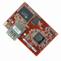
MODULE RABBITCORE RCM3315
Manufacturer
Rabbit Semiconductor
Datasheet
1.20-101-1068.pdf
(160 pages)
Specifications of 20-101-1068
Module/board Type
MPU Core Module
Product
Microcontroller Modules
Core Processor
Rabbit 3000
Clock Speed
44.2 MHz
Interface Type
Ethernet, Serial
Flash
512 KB
Timers
10 x 8 bit, 1 x 10 bit
Operating Supply Voltage
3.15 V to 3.45 V
Board Size
47 mm x 69 mm x 22 mm
Core
RCM3315
Processor Series
RCM3315
For Use With/related Products
RCM3315
Lead Free Status / RoHS Status
Lead free / RoHS Compliant
Other names
316-1114


4.1.1 Memory I/O Interface
The Rabbit 3000 address lines (A0–A18) and all the data lines (D0–D7) are routed
internally to the onboard flash memory and SRAM chips. I/0 write (/IOWR) and I/0 read
(/IORD) are available for interfacing to external devices.
Parallel Port A can also be used as an external I/O data bus to isolate external I/O from the
main data bus. Parallel Port B pins PB2–PB5 and PB7 can also be used as an external
address bus.
When using the external I/O bus for a digital output or the LCD/keypad module on the
Prototyping Board, or for any other reason, you must add the following line at the begin-
ning of your program.
#define PORTA_AUX_IO
// required to enable external I/O bus
4.1.2 Other Inputs and Outputs
The status, /RESET_IN, SMODE0, and SMODE1 I/O are normally associated with the
programming port. Since the status pin is not used by the system once a program has been
downloaded and is running, the status pin can then be used as a general-purpose CMOS
output. The programming port is described in more detail in Section 4.2.3.
/RES is an output from the reset circuitry that can be used to reset external peripheral
devices.
4.1.3 LEDs
The RCM3305/RCM3315 has three Ethernet status LEDs located beside the RJ-45 Ether-
net jack—these are discussed in Section 4.2.
Addiitionally, there are two other LEDs. The
SF
LED at DS3 blinks when data are being
written to or read from the flash mass-storage device. The red
USR
LED at DS3 is a user-
programmable LED, which is controlled by PD0 on the Rabbit 3000’s Parallel Port D. The
sample program FLASHLED.C provided in the Dynamic C
folder
SAMPLES\RCM3300
shows how to set up and use this user-programmable LED.
User’s Manual
29
Related parts for 20-101-1068
Image
Part Number
Description
Manufacturer
Datasheet
Request
R

Part Number:
Description:
COMPUTER SGL-BRD BL2500 29.4MHZ
Manufacturer:
Rabbit Semiconductor
Datasheet:

Part Number:
Description:
COMPUTER SGL-BRD BL2500 29.4MHZ
Manufacturer:
Rabbit Semiconductor
Datasheet:

Part Number:
Description:
DISPLAY GRAPHIC 12KEY PROG OP670
Manufacturer:
Rabbit Semiconductor
Datasheet:
Part Number:
Description:
DISPLAY GRAPHIC 12KEY ETH OP6700
Manufacturer:
Rabbit Semiconductor
Datasheet:

Part Number:
Description:
COMPUTER SINGLE-BOARD BL2030
Manufacturer:
Rabbit Semiconductor
Part Number:
Description:
COMPUTER SGL-BOARD ETH BL2010
Manufacturer:
Rabbit Semiconductor

Part Number:
Description:
MODULE OP6810 W/O ETH/MEM EXPANS
Manufacturer:
Rabbit Semiconductor
Datasheet:
Part Number:
Description:
COMPUTER SINGLE-BOARD BL2020
Manufacturer:
Rabbit Semiconductor
Part Number:
Description:
COMPUTER BL2010 W/FRICTION LOCK
Manufacturer:
Rabbit Semiconductor
Part Number:
Description:
COMPUTER BL2020 W/FRICTION LOCK
Manufacturer:
Rabbit Semiconductor
Part Number:
Description:
COMPUTER SGL-BRD BL2500 44.2MHZ
Manufacturer:
Rabbit Semiconductor
Datasheet:
Part Number:
Description:
COMPUTER SGL-BOARD FULL BL2000
Manufacturer:
Rabbit Semiconductor

Part Number:
Description:
COMPUTER SINGLE-BOARD BL2110
Manufacturer:
Rabbit Semiconductor

Part Number:
Description:
COMPUTER SGL-BRD 29.4MHZ BL2610
Manufacturer:
Rabbit Semiconductor
Datasheet:
Part Number:
Description:
INTERFACE OP6800 512K FLASH&SRAM
Manufacturer:
Rabbit Semiconductor
Datasheet: